Where Did This Idea Come From?
The I Ching Turntable project originated from an interest in how one could generate random numbers in a computer system using a physical event, I have never been convinced that computer generated random numbers are truly random. I was specifically interested in how to replicate the throwing of three coins as in the traditional technique for casting the I Ching, in a way that feels in tune with the Tao.
An early (and fairly crude) idea, that I prototyped in Max/MSP was to simply have a box where you press either 0, 1 , 2 or 3 buttons to represent the number of heads you’ve thrown with three coins. Do this 6 times and the system then displays your generated and transformed hexagrams on an 6×6 matrix of LEDs.
Although the Max patch looked impressive (see Figure 7), this idea was a bit weak. (Max patch can be found here. Open it in presentation mode, I’ve added some explanatory comments)
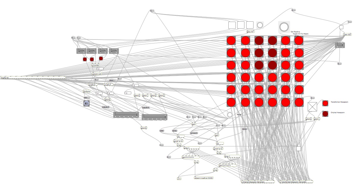
(Figure 1: Patch cord madness.)
I then investigated the possibility of using a Roulette wheel, placing sensors in the pockets that detect where the ball has landed and relay this information to an Arduino. I really like the idea of hacking existing devices, but there were a couple of problems with the Roulette wheel idea;
- Roulette wheels have 37 pockets (in French/European roulette) or 38 (in American roulette), to recreate the throwing of three coins I would have to find a Roulette wheel whose number of pockets is a multiple of 8. As far as I can tell these don’t exist.
- Getting a wheel to spin smoothly and also be able to relay information to a physical location beyond the point on which it is rotating would require some sort of wireless technology. Also, Roulette wheels are finely balanced, thus embedding any sort of Arduino, sensors, infra-red transmitters etc on the wheel itself would be quite likely to disrupt this balance and cause the ball to have a greater probability in landing in certain pockets.
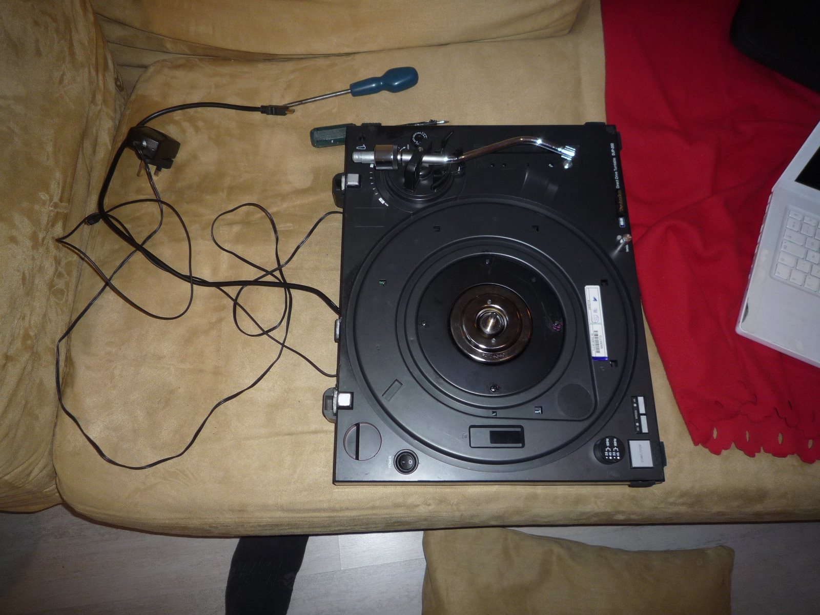
I eventually ditched the Roulette wheel idea, but I didn’t let go of the idea of spinning things. Then I saw an old direct-drive vinyl turntable in my loft…
How I Made The I Ching Turntable
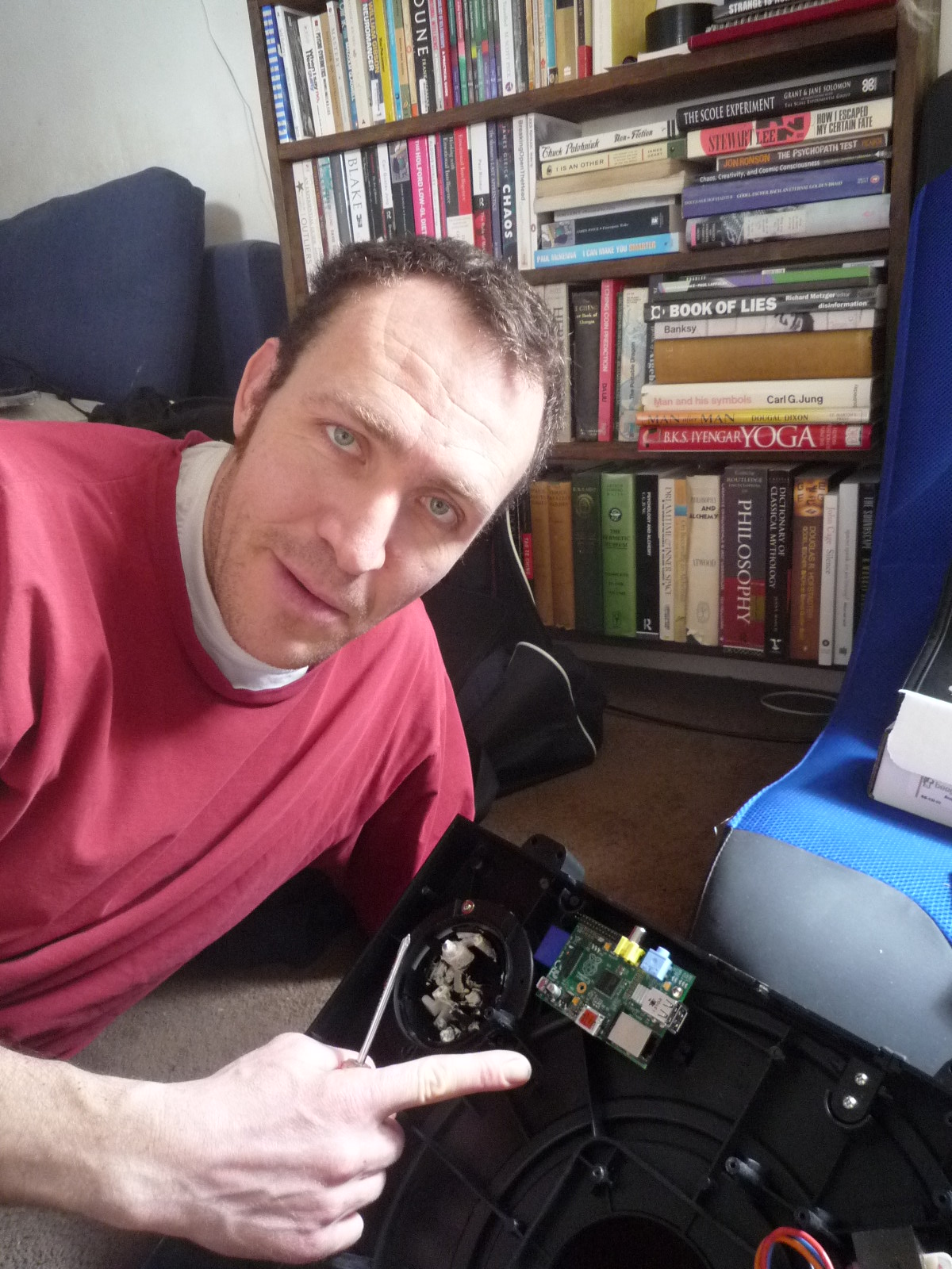
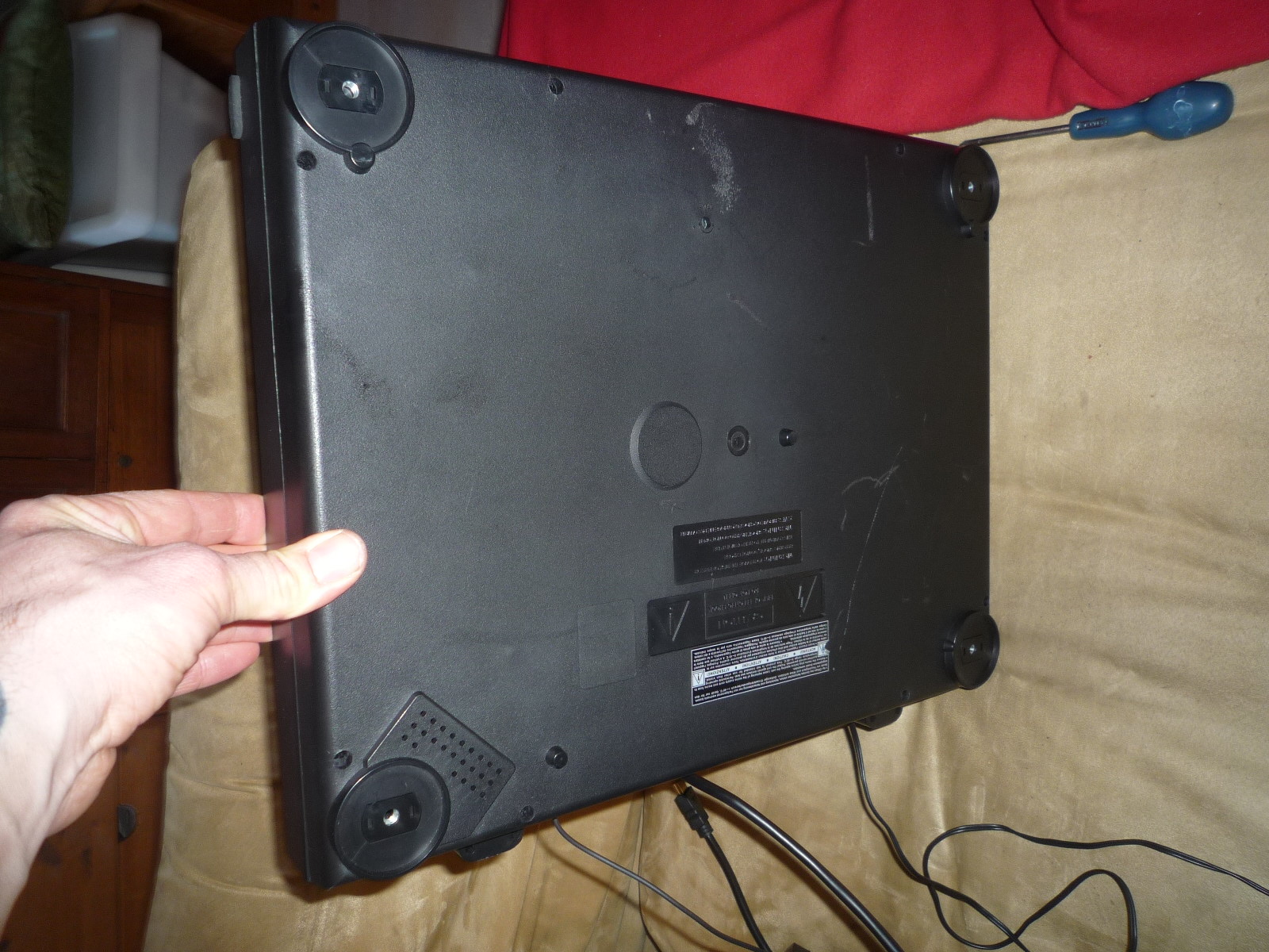
I opened up the turntable casing;
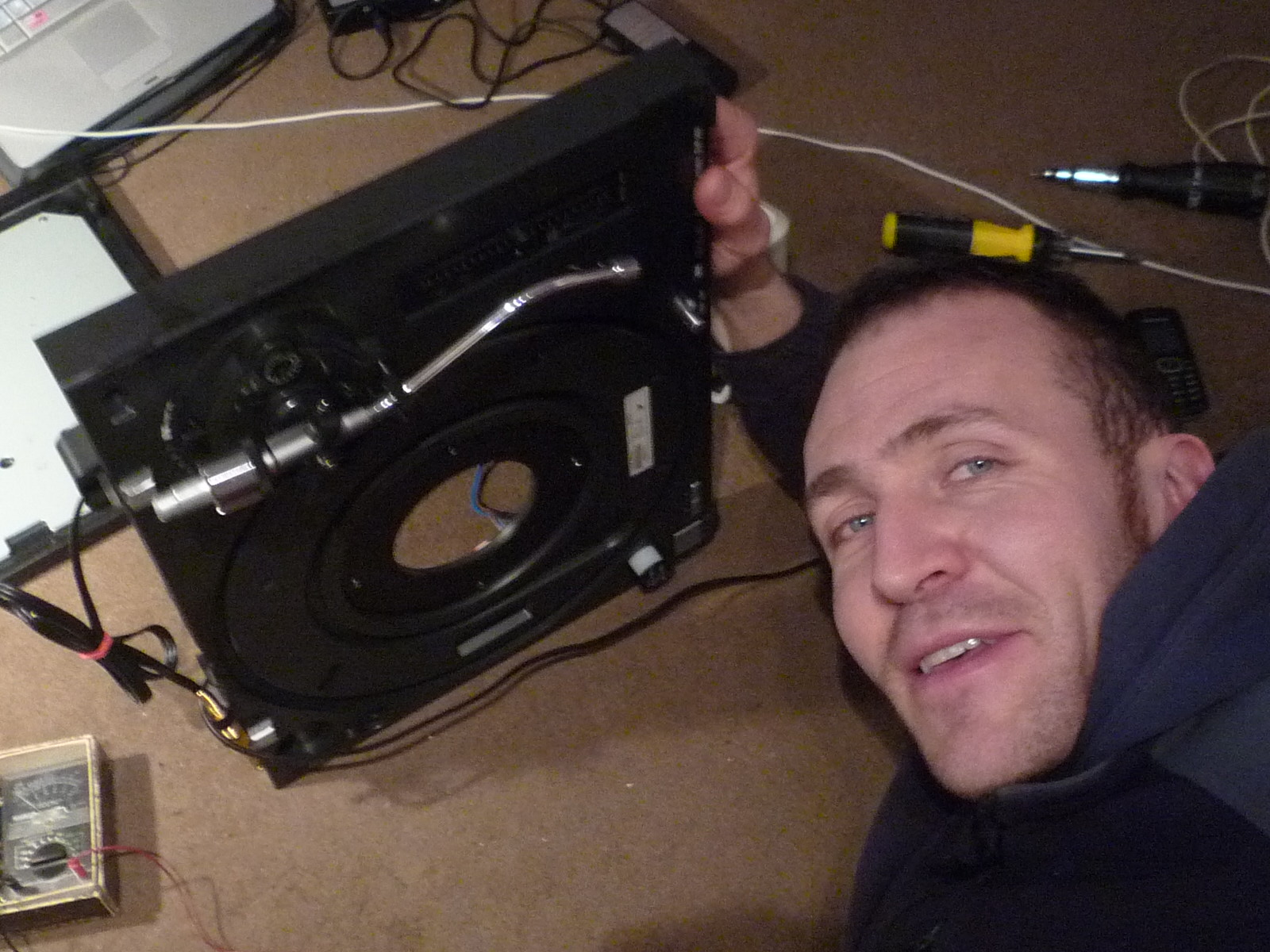
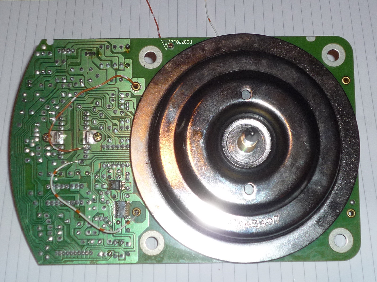
I removed the direct drive motor which is a synchronous motor. The turntable carries permanent magnets. Magnetic coils in the body of the turntable produce a rotating magnetic field which drags the turntable round when the turntable is working normally. A property of such a motor is that if you turn the turntable by hand, the magnets will induce voltages in the magnetic coils. This will occur regardless of the direction of spin.
During each spin of the turntable we sample these voltages as fast as we can using one of the Arduino’s analogue input pins and simply total the readings. We can say confidently that the least significant three bits of this total will be a random number.
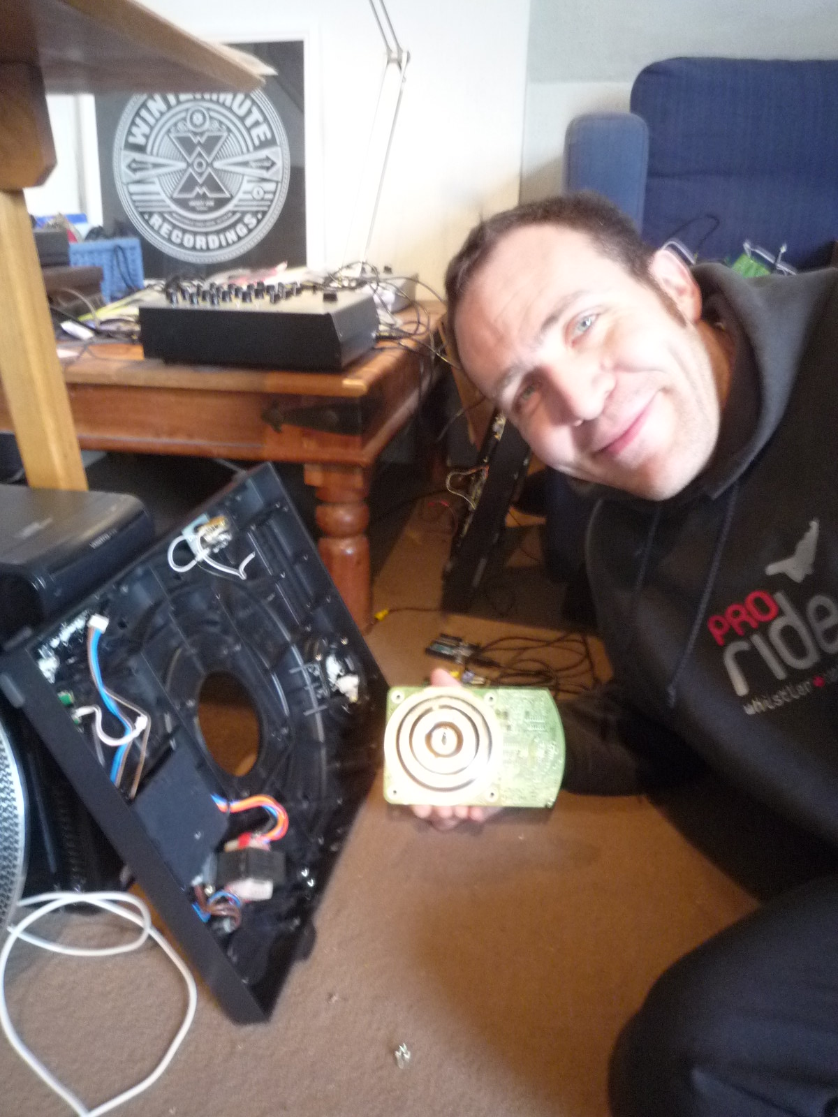
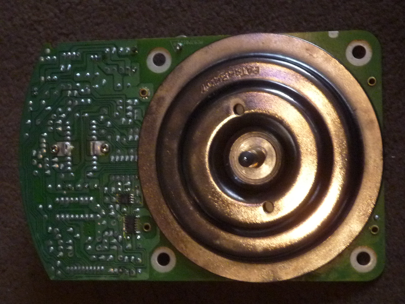
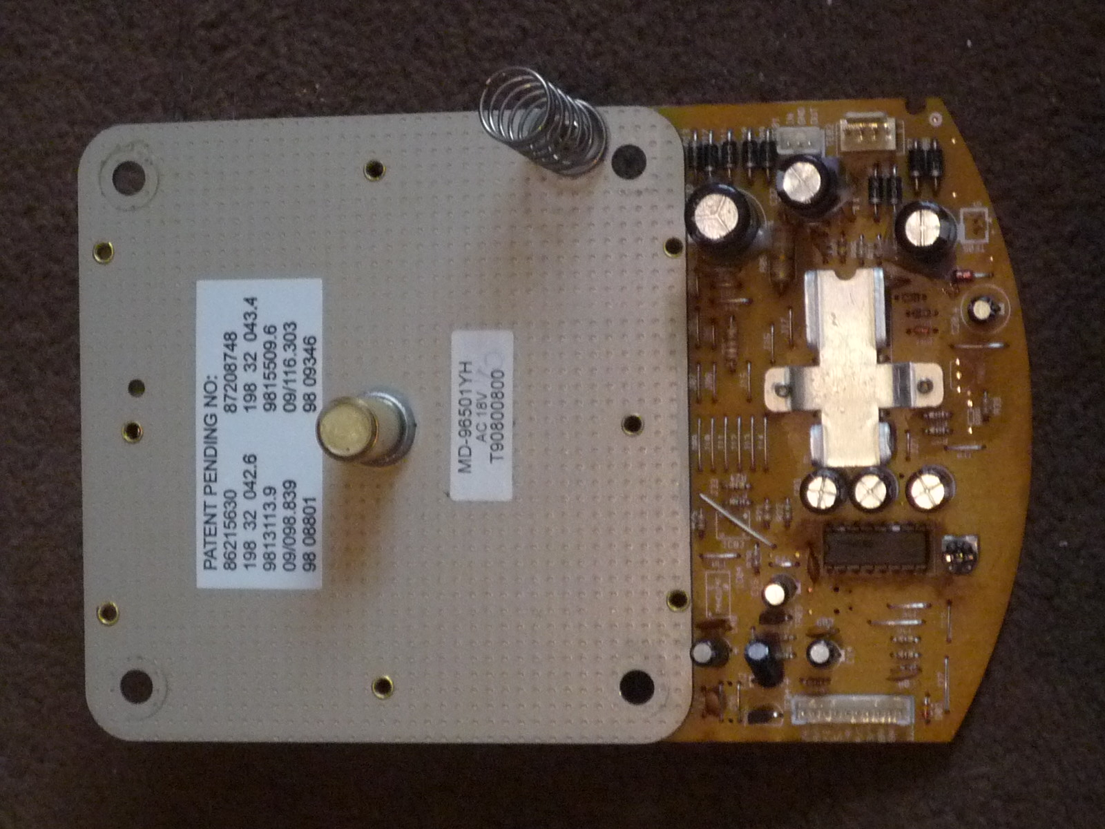
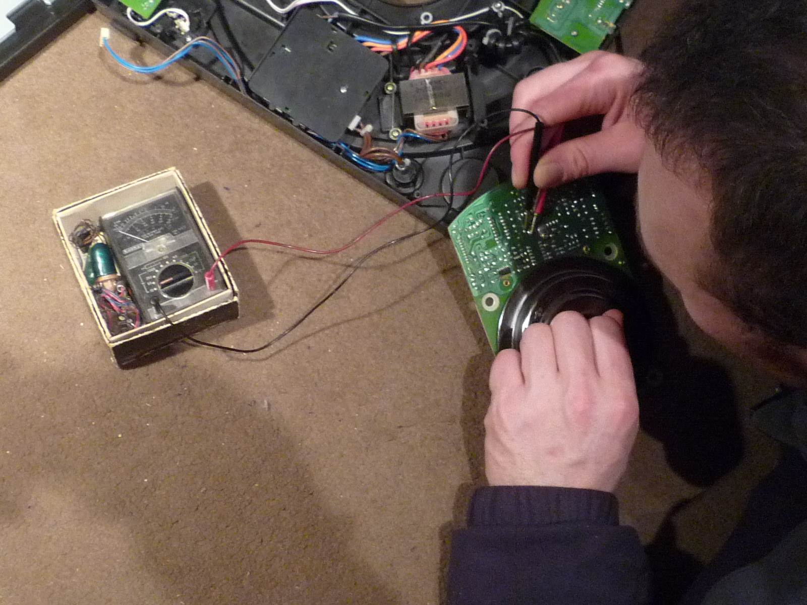
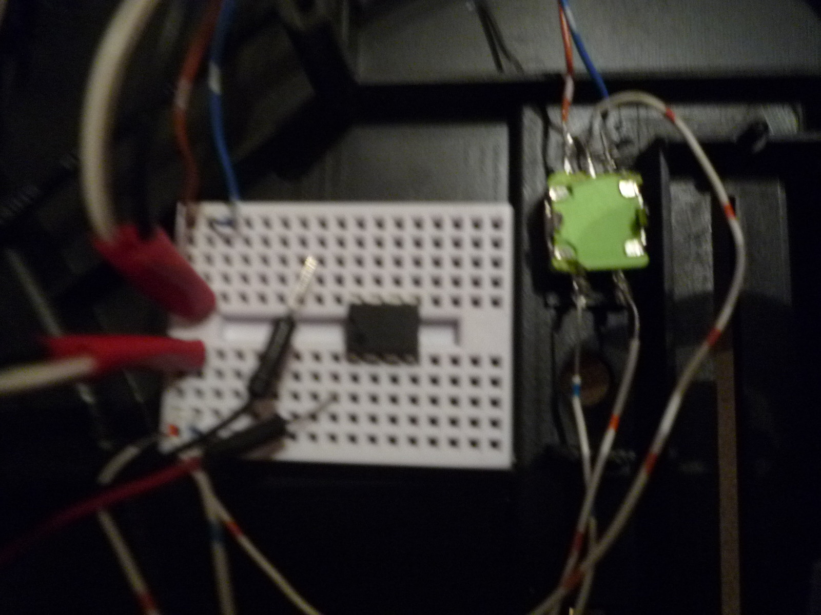
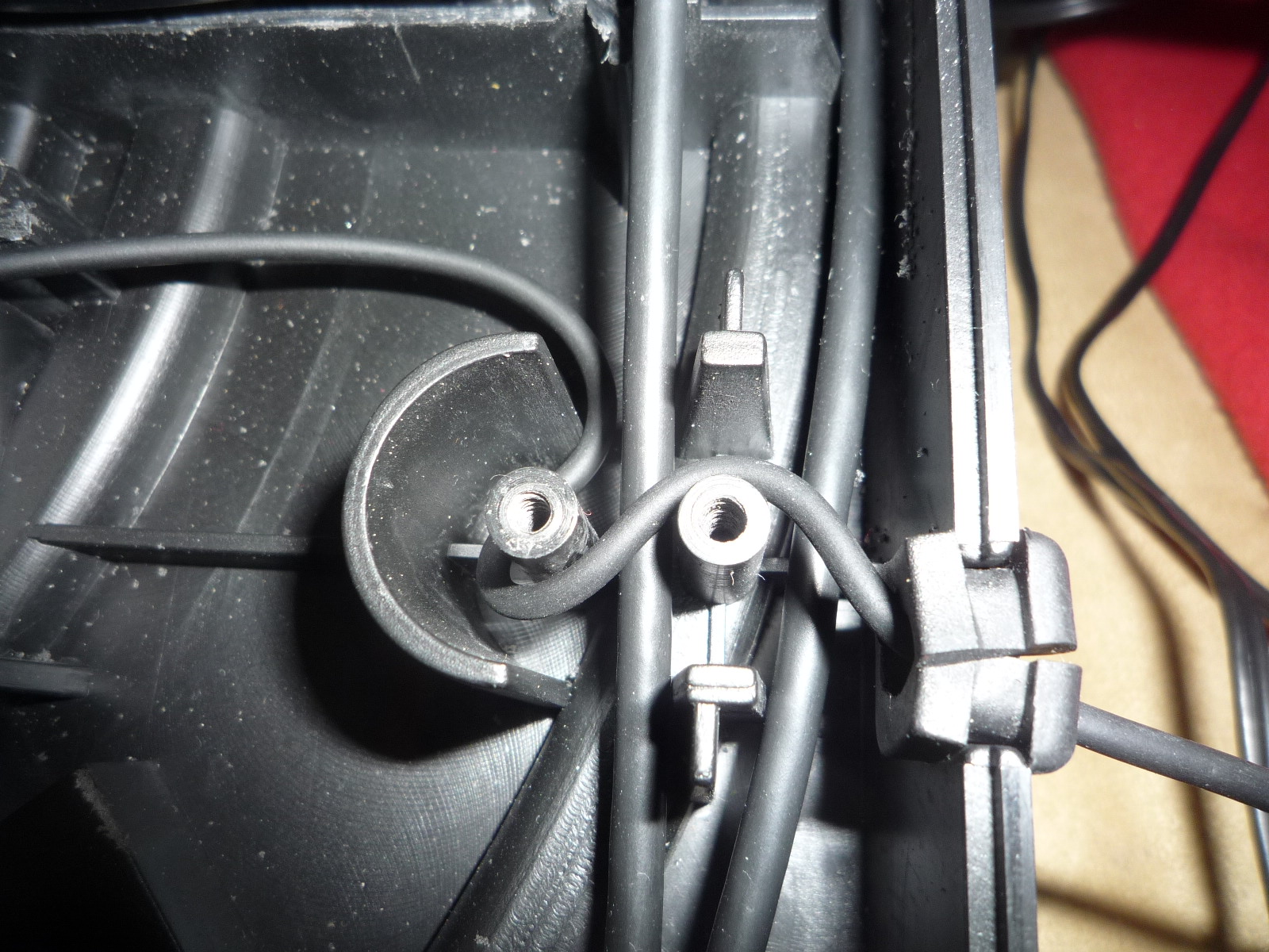
I used a voltmeter to find out which connectors on the direct drive motor produce a current when the shaft of the motor is manually spun;

Once I worked out which connectors they were I soldered wires to them and ran the wires through a pair of very conveniently positioned holes to the other side of the motor;
I then ripped pretty much everything else out of the turntable casing, the power supply, the pitch control, the audio cable, etc;
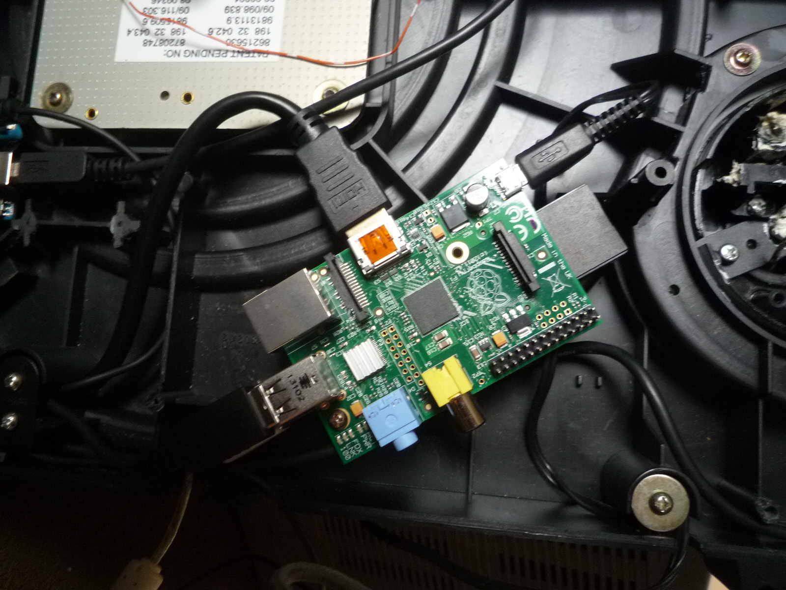
In the spaces now made inside the casing, I found nice places to position the Raspberry Pi;
And the Arduino;
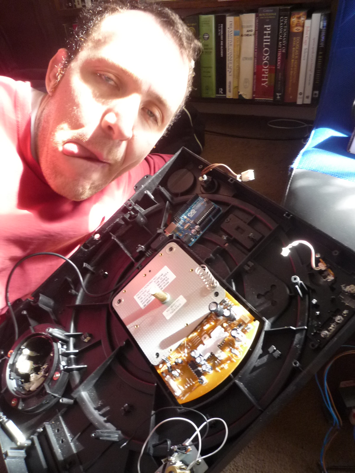
There were existing screw holes in just the right places to attach the Raspberry Pi and Arduino.
I found a hole left from when I removed the pitch control that was the perfect size for my rotary encoder;

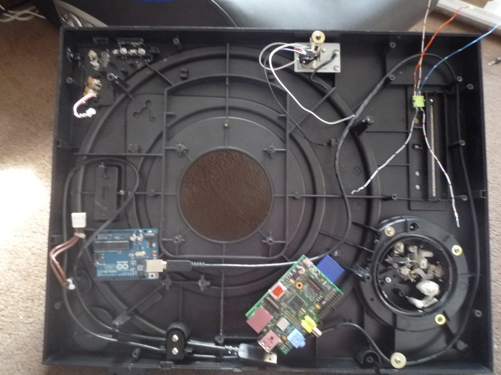
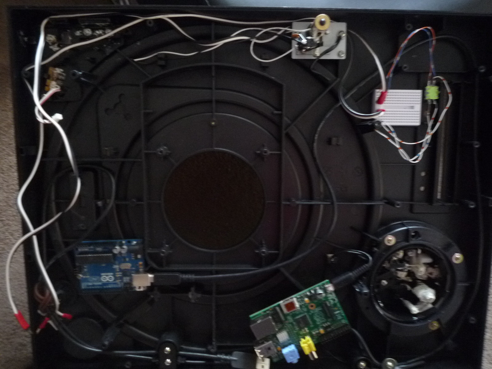
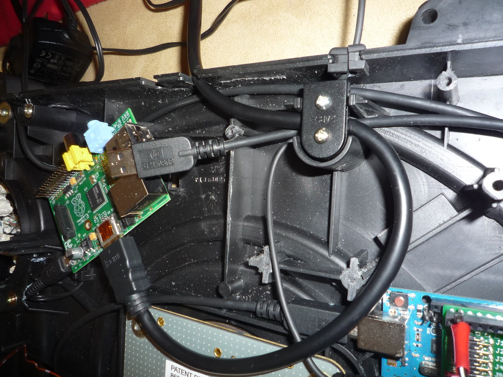
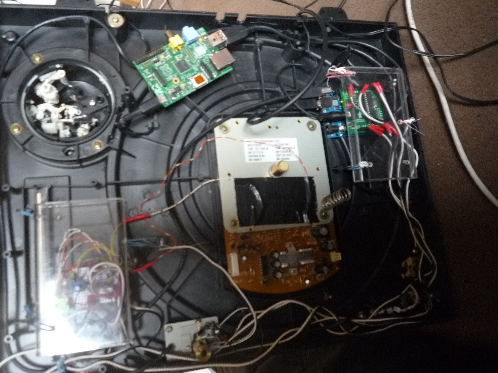
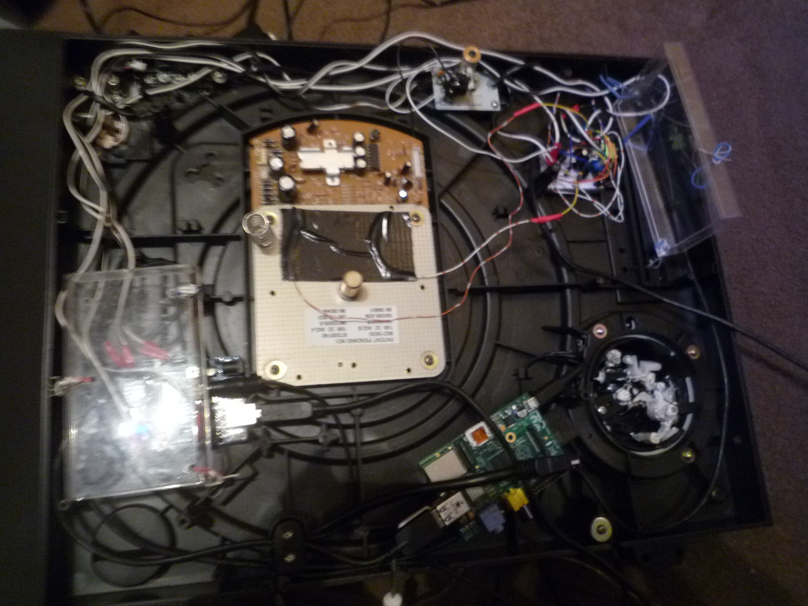
I threaded a USB cable between the Raspberry Pi and the Arduino. Now the inside of the turntable looks like this;
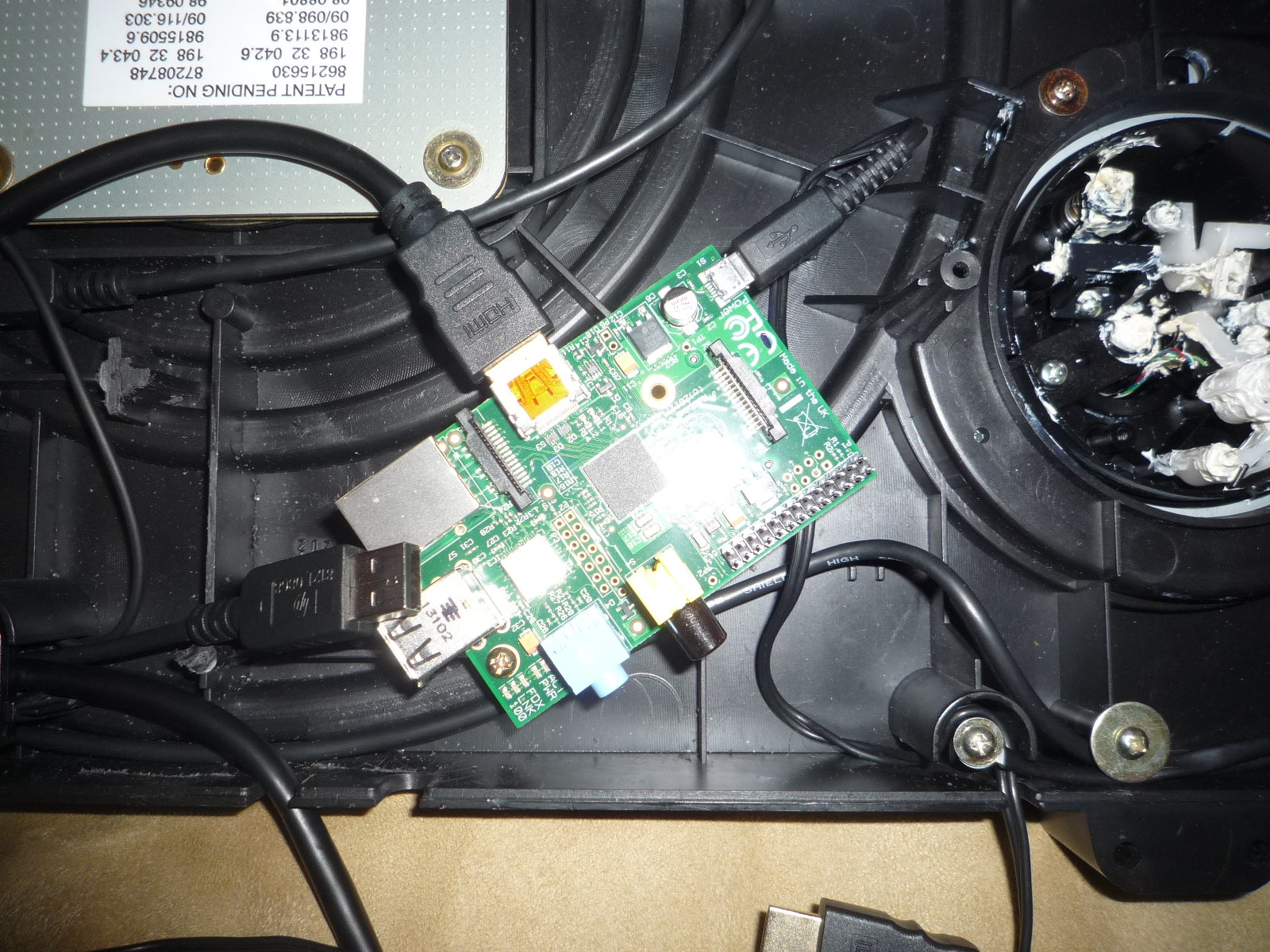
I connected a Blackberry Mini-USB charger and HDMI cable to the Raspberry Pi. I looped the cables through the existing holes at the back. I secured the Blackberry Mini-USB lead it with a screw at the hole to stop it coming loose from the Raspberry Pi if it were to get tugged;
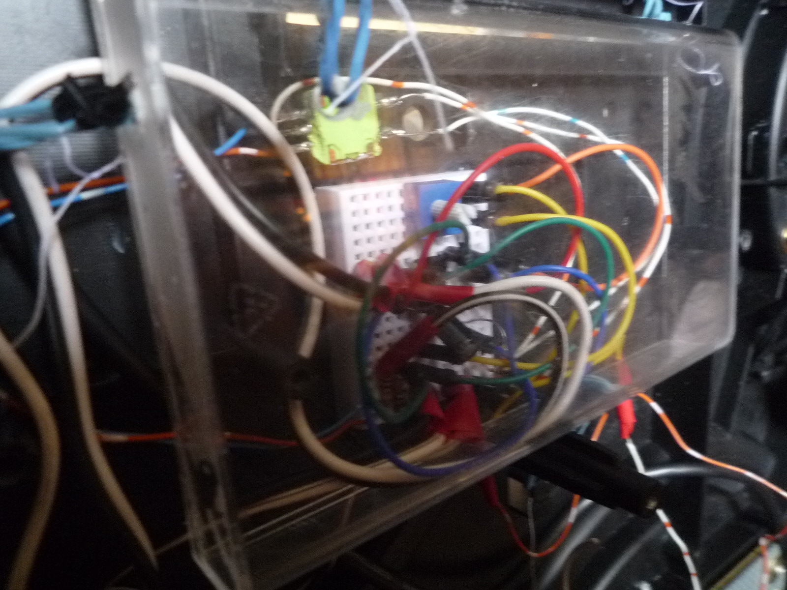
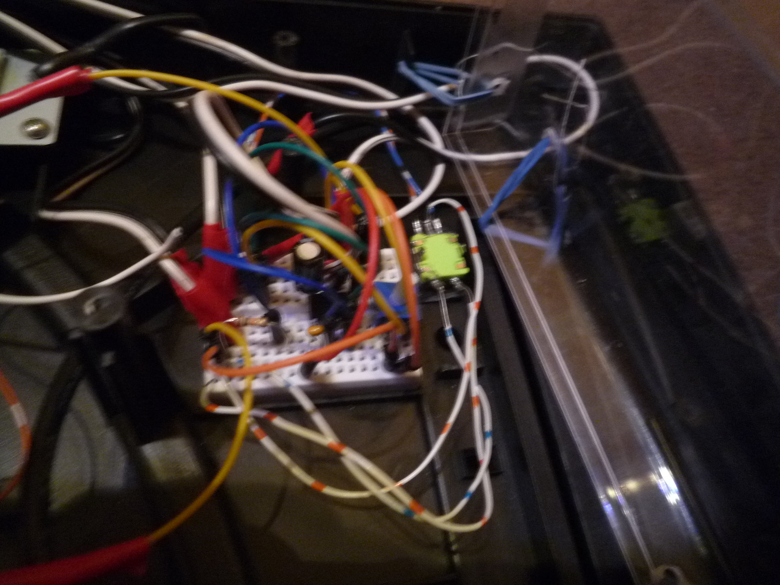
I attached a mini-breadboard next to the rotary encoder, connected the cables from the rotary encoder to it, and connected cables from the breadboard to the Arduino;
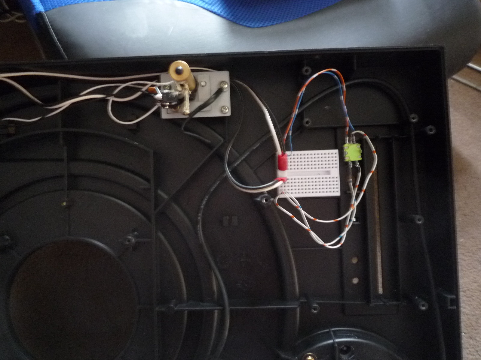
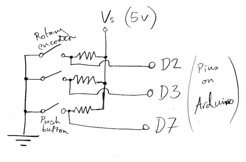
The following diagram is a schematic of the rotary encoder with pushbutton (although this is not exactly as it appears in the picture above as I had yet to add the 10k resistors at that point;
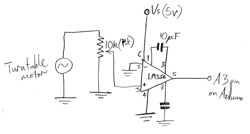
I attached an LM386 amplifier chip to the breadboard, and positioned a 9V battery nearby to power it (Note: The amplifier circuit was later abandoned due to the fact that it was generating large bursts of unexplained noise. I feel that it is still worthwhile to document these steps as I spent much time getting the amplifier chip circuit working);
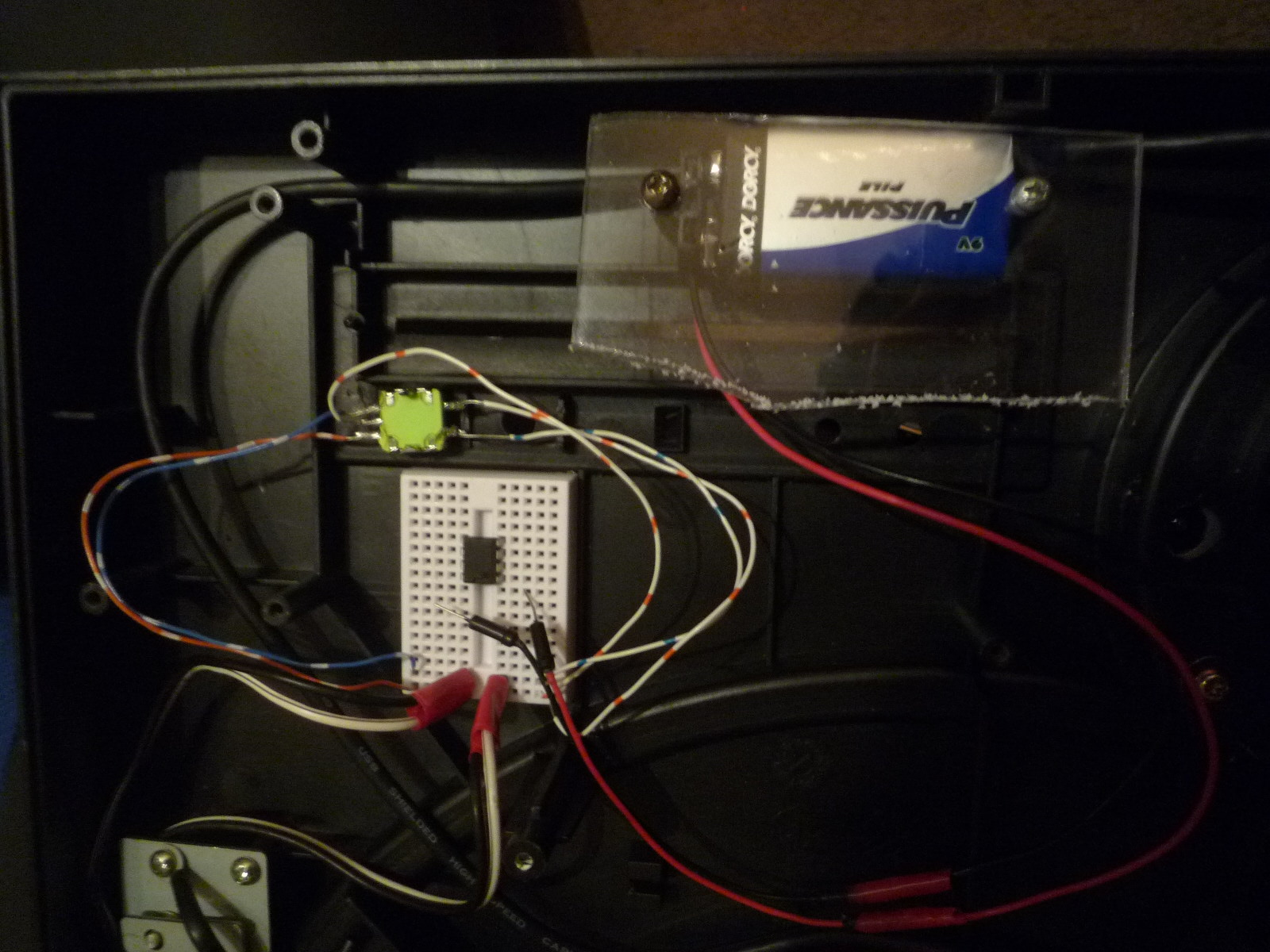
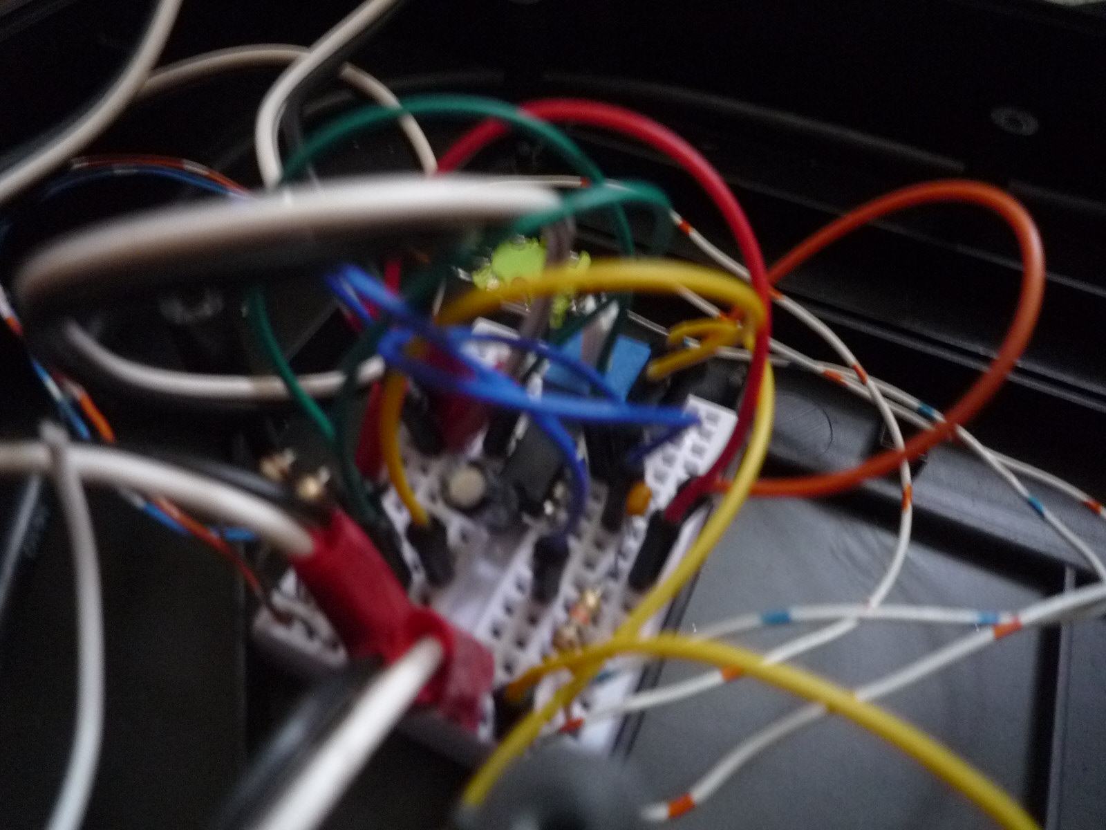
I rigged up the LM386 amplifier circuit like this;
Below is a schematic of the LM386 amplifier chip circuit in the picture above;
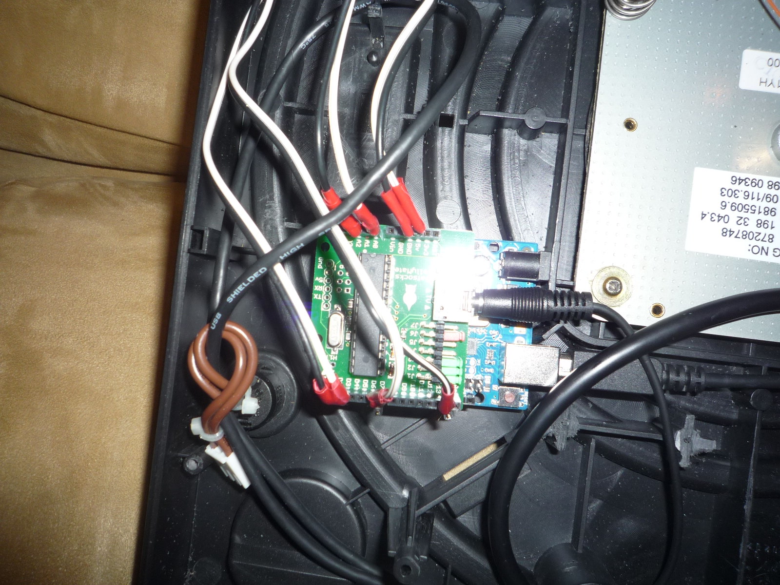
I attached a TellyMate shield to the top of the Arduino and connected long wires to pins;
- D2, D3, D7 and GND (these are for the rotary encoder).
- A3 and A5 (these are to read the voltage that is generated by the spinning of the direct drive motor) Ultimately only A3 was used.
- 5V out and GND (these are to power the LM386 amplifier circuit). I eventually ditched the 9V battery for fear of exceeding the 5V maximum input to the analogue input pins.
- I also attached the RCA video out cable to the TellyMate shield (its socket on the TellyMate shield is clearly labelled “TV” in the picturesbelow). I threaded this through an existing hole, and as with the power supply to the Raspberry Pi, I made sure to secure it in case the cable were to get tugged.

I secured the HDMI cable and the USB lead from the Arduino to the Raspberry Pi in the same place as the RCA video lead from the TellyMate shield to prevent internal damage if the cables were to get tugged;
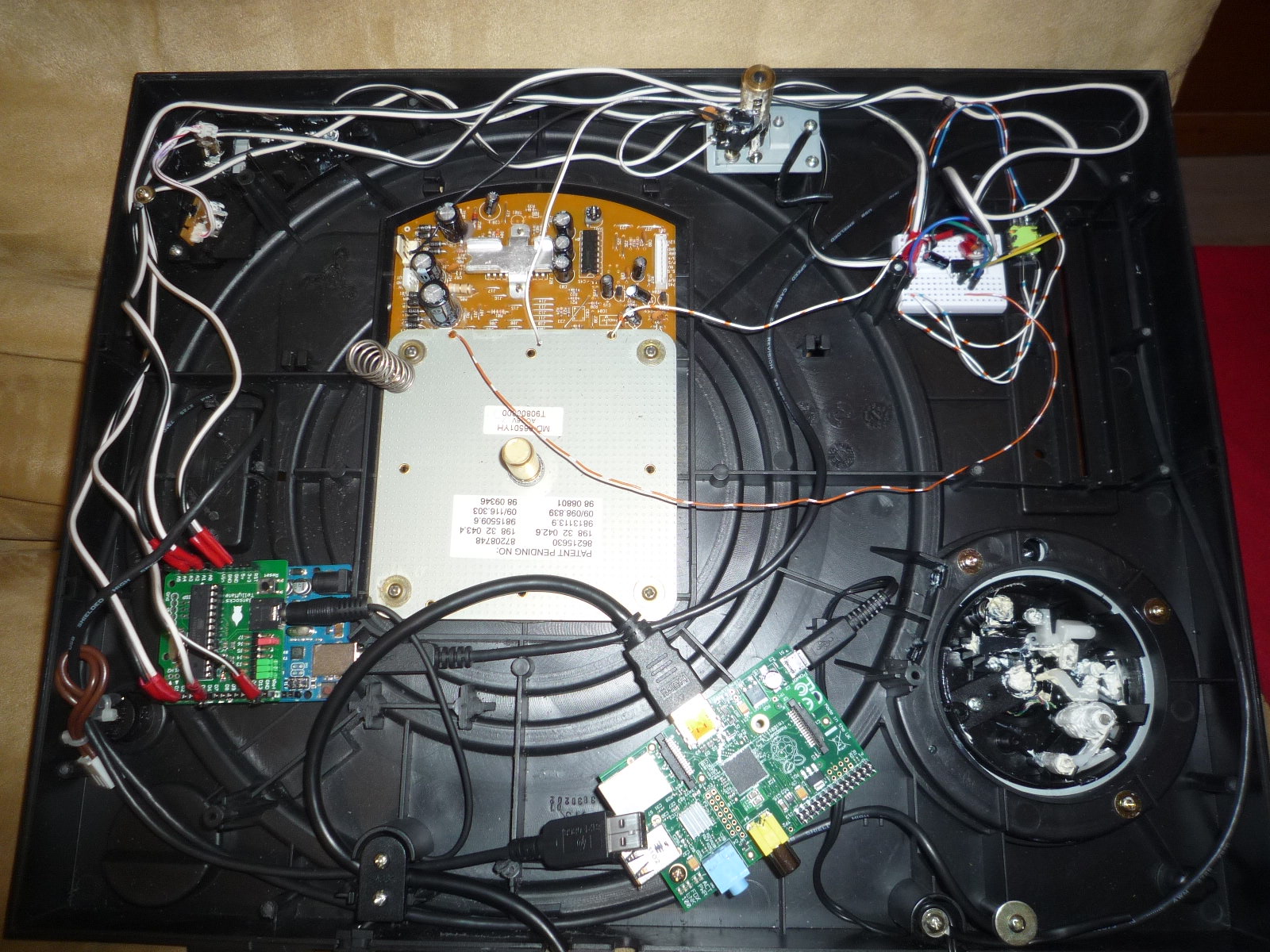
Now the inside of the turntable looks like this;
I attached a USB extension cable to the other port on the Raspberry Pi and threaded it through an existing hole. This is to enable one to connect a keyboard and mouse to the Raspberry Pi once the casing has been sealed;
Now, all of the attached components would be upside down when the turntable is in operation. Thus, to prevent the jumper cables and other components falling out I secured a plastic casing over the top of them with elastic bands to hold the jumper cables in place tightly;

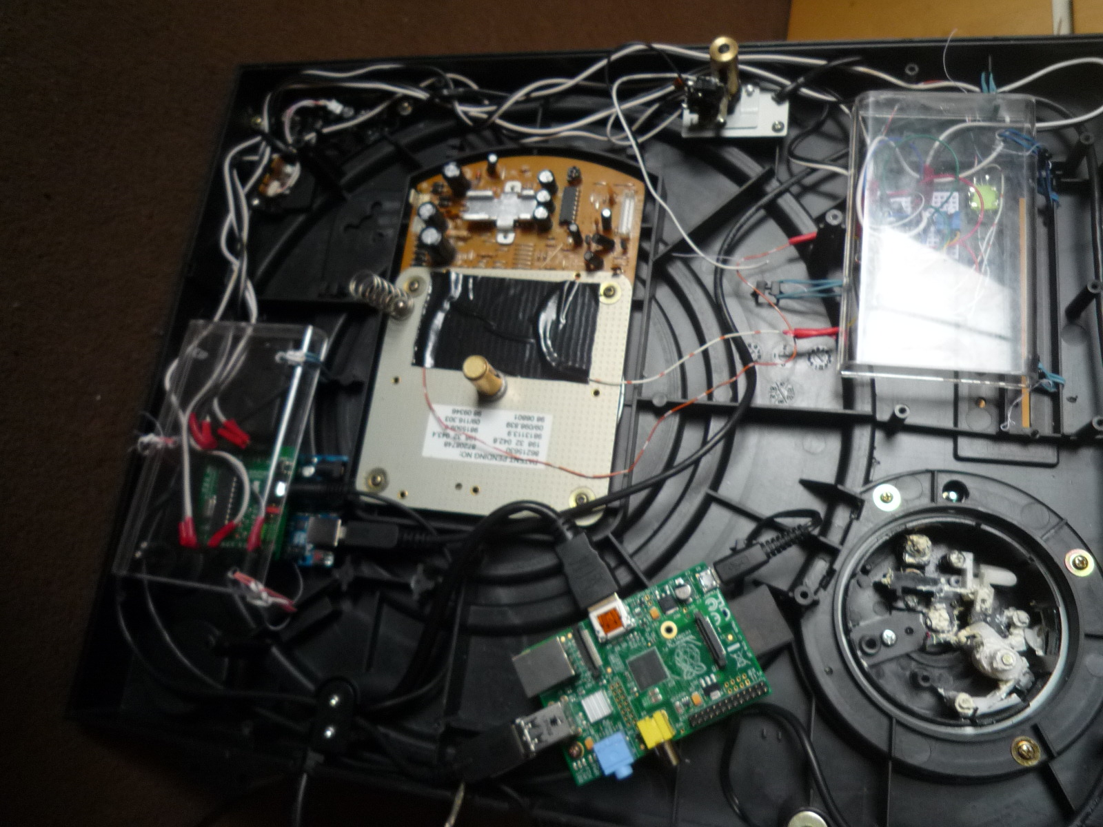
I then re-attached the casing (I eventually opened it up again to bypass the amplifier circuit, but this is essentially the complete hardware setup);
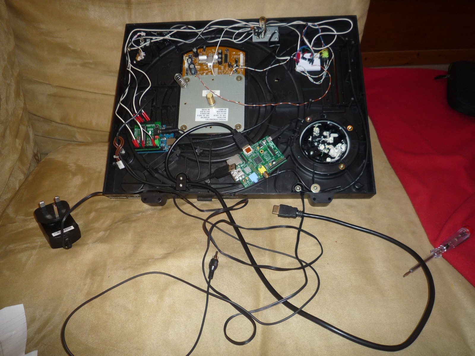
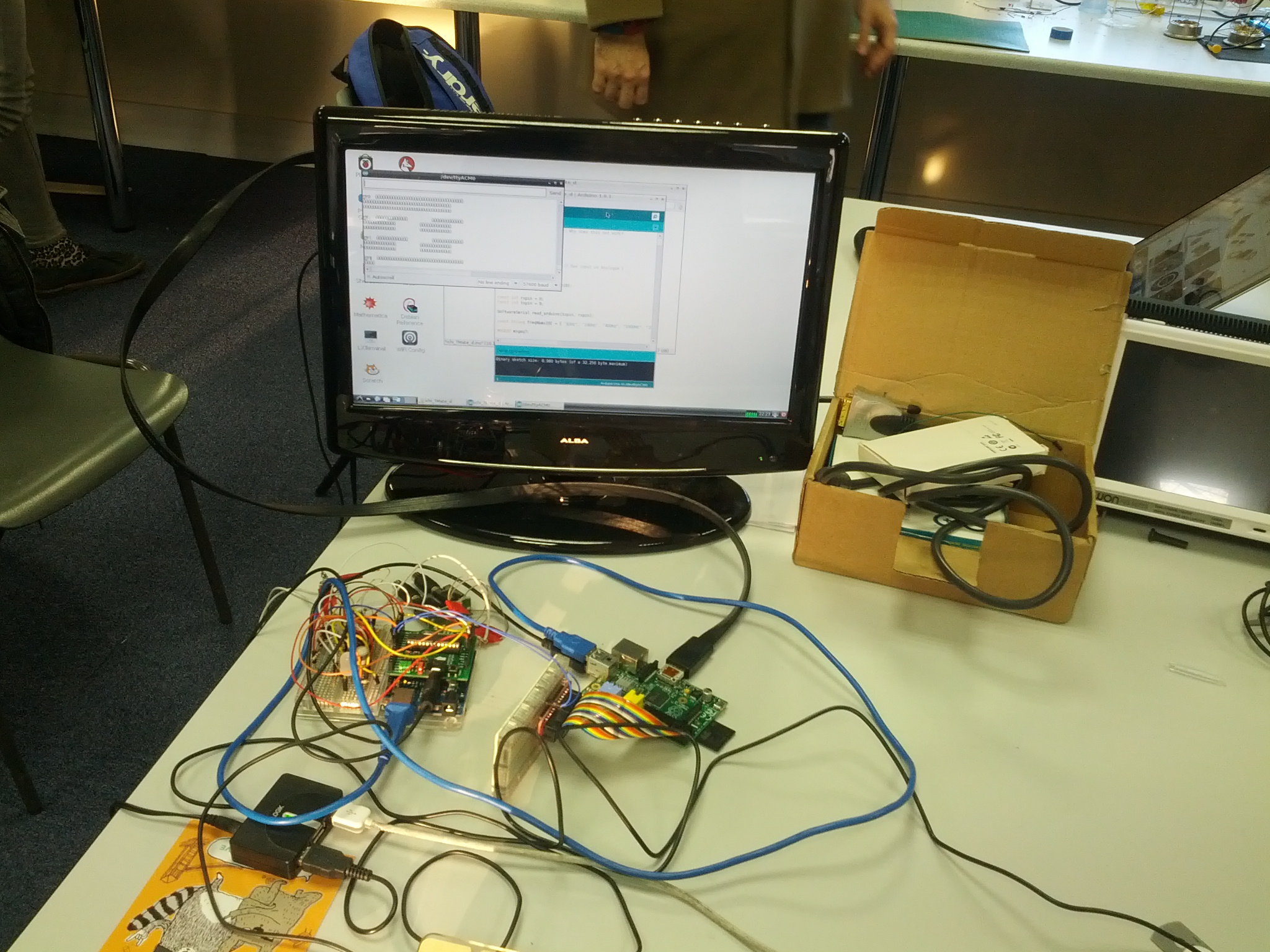
I then re-attached the platter to the turntable, connected the RCA video cable to a CRT monitor, the HDMI cable to an LCD monitor, and plugged the Blackberry charger in to the the wall.
The setup now looks like;
I temporarily connected a keyboard and mouse to the USB cable connected to the Raspberry Pi, and fired up the Processing sketch (source code can be found here).
I then unplugged the keyboard and mouse, this is now a working system. Here is a video of it in operation;
I Ching Turntable Fully Operational from George Haworth on Vimeo.
The functionality is as follows;
- The user spins and stops the platter 6 times.
- After every spin, a line of the generated Hexagram is displayed on the CRT monitor, starting at the bottom and working up.
- When the 6th line has been generated, the LCD monitor displays the full reading.
- The rotary encoder scrolls through the text, clockwise to go down, counterclockwise to go up.
- The push button on the rotary encoder resets the system.
The image at the start (or whenever reset is pressed) was taken from; http://iching.egoplex.com/mandalas.html
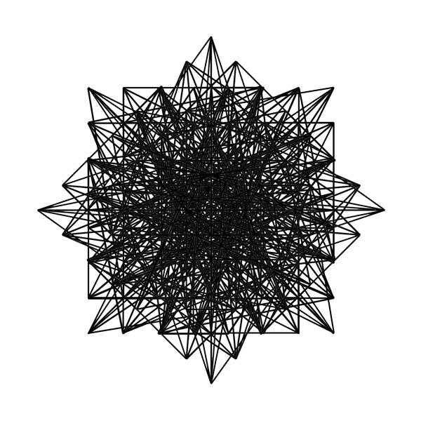
(Figure 2: Mandala geometrically derived from the King Wen sequence.)
“These mandalas (images) are geometrically derived from the King Wen sequence in various permutations. The key thing to remember is that they are direct visual representations of the i-Ching and not simply artistic interpretations.” (Quote from: http://iching.egoplex.com/mandalas.html)
One observer of the system commented that the visuals on the LCD screen on the right in the video (I Ching Turntable Fully Operational) appeared to represent chaos, and the lines appearing on the CRT screen on the left represented order emerging out of the chaos. This was not an intended effect, but I liked the comment so I wanted to relay it here (without sounding too pretentious).
Materials Used
- 1x Direct Drive Turntable (heavily gutted).
- 1x Arduino Uno.
- 1x TellyMate Shield.
- 1x Raspberry Pi Model A (with 4GB SD card).
- 1x Mini Breadboard.
- 1x CRT Monitor.
- 1x LCD Monitor.
- 1x USB Cable (to connect Arduino to Raspberry Pi).
- 1x USB extension cable (to connect Raspberry Pi to keyboard and mouse when the casing is closed)
- 1x RCA to mono-jack cable (to connect TellyMate shield to CRT monitor).
- HDMI cable (to connect Raspberry Pi to LCD monitor).
- Blackberry Mini-USB charger.
- Rotary encoder (notched with push button).
- 3x 10k Ohm resistors
- 1x LM386 amplifier chip
- 1x 220 uF capacitor
- 1x 10 uF capacitor
- 1x 0.1 uF capacitor
- 1x Potentiometer.
- A whole bunch of jumper cables and wires.
- 2x plastic casings (i.e. half a Ferrero Rocher box) and elastic bands to hold them on.
Diagrams and Schematics
Here is an attempt to produce a Fritzing diagram of the breadboard view of the entire setup;
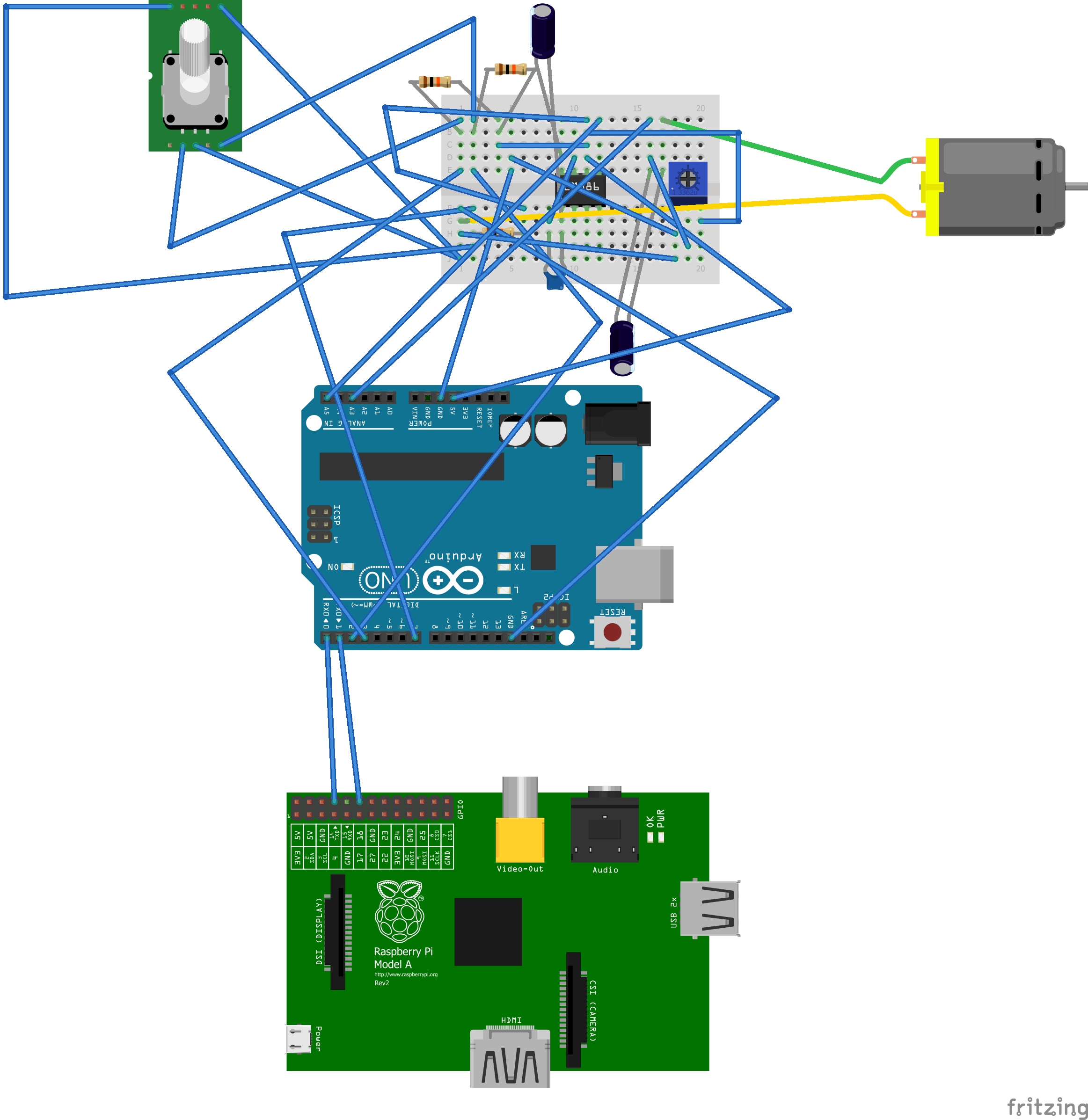
(Figure 3: Fritzing mess, arghhhh!!!)
Not to mention that this is impossibly messy, and probably wrong. There were a few problems with using Fritzing;
- There is no symbol for the TellyMate shield.
- I couldn’t find a way to connect the Raspberry Pi and Arduino via a USB cable, so I used the GPIO pins.
- Fritzing seems to be unable to convert even very simple breadboard diagrams into correct schematics.
I don’t like Fritzing, so all the schematics here have been hand drawn.
Problems Encountered / Learning Experiences
1. Noise
As I mentioned previously, one of the initial problems I encountered when passing the output from the direct drive motor through the LM386 amplifier circuit was that it would generate bursts of noise if the casing was knocked, and often just give out random noise bursts spontaneously.
Here is a video of me testing the system which demonstrates this;
Testing for Noise from George Haworth on Vimeo.
The numbers flowing onto the monitor are direct readings of the voltage being read by the Arduino from the direct drive motor. When the motor is manually spun there is a burst of data as intended. However the video also demonstrates that a burst of data also occurs if the casing is knocked. This would lead to a line of a hexagram being generated unintentionally.
I first tried to address this problem by setting a threshold value. Readings over this threshold were to be regarded as a spin and those below as a noise burst, in order to stop lines being generated by bumping the casing. However there would sometimes be a few very large bursts of voltage from even small bump, so this approach wouldn’t always be reliable.
I then considered the fact that bumps are very short impulses of influence, normally less than 300-500ms, and spins are usually at least 1 second. I accounted for this fact in the Arduino code here;
if (inABurst && (millis()-lastAnalSeen) > silenceDelay) {
  // A burst of analogue input has ended
  inABurst=false;
  long burstLength = lastAnalSeen-firstAnalSeen;
  lastAnalSeen=MAXLONG;
  if (burstLength<minBurstLength) {
    // This noise burst stuff was introduced when I was struggling with noise problems.
    // It may well be redundant now that I've bypassed the LM386 amplifier circuit
    // that appeared to be the source of much of this noise.
    #if DIAGM
      Serial.println("");
      Serial.println("Noise burst");
    #endif
  } else {
    // Display a yin or yang
  }
}
But ultimately, even with this clever code, the system would still generate large bursts of noise spontaneously. I really wanted the system to be reliable, and the only solution seemed to be to disconnect the amplifier circuit. The above code remained however as a safety mechanism.
2. File handling in Processing
I had cut and pasted the Wilhelm translation of the commentary on the I Ching from this website and formatted it carefully into a single file with markers so that the commentary on a given hexagram could be located with Processing’s equivalent of the strpos() function in PHP, or strstr() function in C++.
It is only 400k bytes long, but the Raspberry Pi does not seem to offer any way of reading the entire file into a string. When I tried to read it with a loop of readLine() commands it was taking forever. So I had to write a program to read this monolithic file and split it into 64 separate files, one for each hexagram.
3. Rotary encoder latency
The Processing code on the Raspberry Pi was extremely slow to respond to the rotation of the rotary encoder which is used to scroll through the text. No immediate solutions to this issue sprang to mind, I have left it as an open problem.
4. Arduino limitations in handling arrays of strings
I had an array of longer English names for the hexagrams (see kwNamL[] in IChing_Processingcode.pde). This takes up a very modest 2630 bytes of source code and presumably about the same when compiled. When the table was incorporated in here, it compiled and uploaded fine but simply failed to run.
When the table was reduced to just 10 elements, it worked fine. But with the full 65 elements in the table it didn’t work. Checks were made to determine the critical number of elements. This seemed to be dependent on the amount of other code in the Arduino sketch. In one test using the determined critical number of elements (in this case 47), compiling reported a sketch size of 6768 bytes (of a 32,256 byte maximum). Thus according to the compiler the sketch was well within the maximum limits, but we still were getting run time problems.
I have left this as another open problem.
5. Serial communication to multiple devices
I had to send serial data from the Arduino to both the TellyMate shield and the Raspberry Pi. The communication between the Arduino and the TellyMate shield occurred via the D0 and D1 pins (these are the default pins for sending serial data).
I was able to send serial data via another pair of pins, by using the AltSoftSerial library. However I was not able to work out how to see this data on the GPIO pins of the Raspberry Pi.
Here is a photo of me trying to do this (Here I am testing the communication using a 555 timer chip circuit similar to the one described in Figure 8, only with an ordinary resistor in place of the posistor);
I ended up having to use a single serial channel to send data to both the TellyMate shield and the Raspberry Pi.
There were four messages that the Raspberry Pi required;
- Clear screen, where the Raspberry Pi could pick up the actual signal being sent to the TellyMate.
- Two of the message types involved very small amounts of data, which could be output as cursor addressing sequences. These would do nothing on the TellyMate except move its cursor.
- I decided that I wanted every analogue input reading to be sent to the Raspberry Pi. I could see no way of making it invisible on the TellyMate output. The best that can be done is start the output at the bottom right of the screen. Characters which should theoretically be off the screen in fact overlay each other at the bottom right corner. As soon as they are displayed they are blanked. This produces visible flashing but at least it corresponds to the turntable being turned.
6. Software setup on the Raspberry Pi
Installing Processing on the Raspberry Pi was not a trivial undertaking. Fortunately I found a very good online tutorial for how to do this; http://scruss.com/blog/2014/01/07/processing-2-1-oracle-java-raspberry-pi-serial-arduino-%E2%98%BA/
7. Working with actual objects in 3 dimensions with gravity
It was a nice change from the abstract world of computer code, to have to think about real objects in real space. Issues such as how to best embed the Arduino and Raspberry Pi to take advantage of existing screw holes in the casing. Then realising that they would now be upside down when the turntable is operation, how would I stop the jumper cables from falling out over time. I very much enjoyed this side of the project.
Source Code
(This is also available to download here, along with the entire collection of 64 text files of the Richard Wilhelm Translation of the I Ching.)
Arduino Code
//  I Ching Turntable Project - Arduino code

//  George Haworth  2014 Mar 25  Presentation version

//  The Arduino captures the random number data, generates hexagrams and displays them via a
//  TellyMate on a TV screen. Using the same serial channel as it uses for the TellyMate, it sends
//  data to the Raspberry Pi (R.Pi) for more extensive displays of the full text reading.

const char* kwNamS[65] = {          // Short names of the hexagrams in the sequence created by
                                    // King Wen of Zhou (1152 - 1056 BCE)
        "",                         // King Wen starts at 1
        "Ch'ien",     "K'un",       "Chun",  "Meng",    "Hsu",       "Sung",      "Shih",    "Pi",      //   8
        "Hsiao Ch'u", "Lu",         "T'ai",  "P'i",     "T'ung Jen", "Ta Yu",     "Ch'ien",  "Yu",      //  16
        "Sui",        "Ku",         "Lin",   "Kuan",    "Shih Ho",   "Pi",        "Po",      "Fu",      //  24
        "Wu Wang",    "Ta Ch'u",    "I",     "Ta Kuo",  "K'an",      "Li",        "Hsien",   "Heng",    //  32
        "Tun",        "Ta Chuang",  "Chin",  "Ming I",  "Chia Jen",  "K'uei",     "Chien",   "Hsieh",   //  40
        "Sun",        "I",          "Kuai",  "Kou",     "Ts'ui",     "Sheng",     "K'un",    "Ching",   //  48
        "Ko",         "Ting",       "Chen",  "Ken",     "Chien",     "Kuei Mei",  "Feng",    "Lu",      //  56
        "Sun",        "Tui",        "Huan",  "Chieh",   "Chung Fu",  "Hsiao Kuo", "Chi Chi", "Wei Chi", //  64
};

//  There is also a set of longer English names - see kwNamL[] in IChing_Processingcode.pde - this takes up a very
//  modest 2630 bytes of source code and presumably about the same when compiled. When the table was
//  incorporated in here, it compiled and uploaded OK but gave curious errors at run time.

const int  kingWen[] = {
              2, 24,  7, 19, 15, 36, 46, 11, 16, 51, 40, 54, 62, 55, 32, 34,
              8,  3, 29, 60, 39, 63, 48,  5, 45, 17, 47, 58, 31, 49, 28, 43,
             23, 27,  4, 41, 52, 22, 18, 26, 35, 21, 64, 38, 56, 30, 50, 14,
             20, 42, 59, 61, 53, 37, 57,  9, 12, 25,  6, 10, 33, 13, 44,  1,
};

// Translation from my number system to King Wen sequence, the position in this array denotes the binary number
// of the hexagram where yin, "--   --" is zero and yang, "-------" is one. The bottom line of the hexagram
// is taken to be the least sigificant bit and the top the most.

#define DIAGM 0                // Set to true to enable diagnostic messages

#define MAXLONG 0x7FFFFFFF     // Hexadecimal maximum value of a signed long variable

#define CHAR_ESC '\x1B'

const int  encoderPinA = 2;    // ) Rotary encoder Gray code pins.
const int  encoderPinB = 3;    // )
const int  resetPin  = 7;      // Push button on the rotary encoder.
const int  analInPin = 3;      // Analogue input from the turntable.

      int  resButState;        // The current reading from the reset pin.
      int  encoderPrevState;   // Previous state of the encoder.

      int  currAnal = 0;             // Current value of the analogue input.
      int  inABurst;                 // Currently in a burst of analogue input.

      long lastAnalSeen  = MAXLONG;  // Millisecond count at which the last analogue number has been seen
                                     // within the current burst of data.
      long firstAnalSeen;            // Millisecond count at which the first analogue number has been seen
                                     // within the current burst of data.
const long minBurstLength = 300L;    // Analogue voltage readings below this millisecond duration are discarded.
const long silenceDelay   = 300L;    // Assume turntable has stopped if no readings seen in last n milliseconds.

      int  quiAnal;                  // Quiescent level of analInPin.

      long totAnal;            // This anal means analogue. It is a total of the analogue readings.
                               // It is meaningful during setup() but during actual running its value
                               // is meaningless but we can rely on the least significant three bits
                               // being random.

      int  anal[8];            // This anal means analysis.  It is simply counts of how many times
                               // each random value is seen.

      int  yyLine;             // Next line of hexagram to display. 0 = bottom
                               // (yy suggests y co-ordinate as well as yin-yang)
#define XNX   0                // X co-ordinate for drawing hexagram

      int  hexNo[2];           // Current hexagram and its transform in my notation - see kingWen[] above
      int  showingXfm;         // Obsolete code - dates from a version of this program that displayed
                               // both the hexagram and its transform
      int  xx=0;               // Controls scrolling in diagnostic option

// -------------------------------------------------------------------------

void setup() {    // Most of the coding time is spent working on loop(). So I like that to be
                  // close to the data definitions. setup() can be pushed out of the way to the bottom.
  int j;

  pinMode(encoderPinA, INPUT);
  pinMode(encoderPinB, INPUT);
  pinMode(resetPin,    INPUT);
  resButState = digitalRead(resetPin);
  encoderPrevState=encoderState();
  cursor_move(13,encoderPrevState);

  Serial.begin(57600);
  clear_screen();

  int quiSamps = 120;
  totAnal=0;
  for (j=0; j<quiSamps; j++) totAnal += raw_analog();
  quiAnal=totAnal/quiSamps;
  totAnal=0;
  // The turntable produces AC output peaking at about +/- 1 volt so I've taken full advantage of it and
  // superimposed its output on a fixed level of about 2.5 volts. The above loop determines exactly
  // that this fixed level is. The unnecessarily large value of quiSamps dates from the time when I
  // had an amplifier in the circuit and I was investigating noise problems. Once I bypassed the LM386
  // amplifier chip circuit, this noise mostly disappeared.

  if (resButState == LOW) {   // Another way of producing diagnostic output - this stuff is only output
                              // if the reset button is held down during boot up.
    for (j=1; j<=64; j+=10) {
      Serial.print(j,DEC); Serial.print(" ");
      Serial.print(kwNamS[j]);   Serial.print(" | "); Serial.print  (kwNamS[j+1]); Serial.print(" | ");
      Serial.print(kwNamS[j+2]); Serial.print(" | "); Serial.println(kwNamS[j+3]);
    }
    Serial.println(quiAnal);
  }
}

// -------------------------------------------------------------------------

int raw_analog() {
  int j = analogRead(analInPin);
  #if DIAGM
    Serial.print(j); Serial.print(" ");    // When I had this enabled, the totAnal values were much smaller
    // Conclusion: the time taken to do the Serial.print() was causing analogue readings to be missed
    if (!(++xx %20)) {
      Serial.println("");
    }
  #endif
  return j;
}

int encoderState() {           // Read both encoder pins and return them as a single value
  return digitalRead(encoderPinB) | (digitalRead(encoderPinA) <<1);
}

void cursor_move( uint8_t row , uint8_t col ) {     // Yrc
  Serial.write( CHAR_ESC ) ;
  Serial.write( 'Y' ) ;
  Serial.write( 32 + row ) ;
  Serial.write( 32 + col ) ;
}

void clear_screen() {
  Serial.write(CHAR_ESC); Serial.write("E");
  // This is the case where the TellyMate and the Raspberry Pi can use the same sequence
  yyLine=0;  hexNo[0]= hexNo[1]= showingXfm= 0;  inABurst=false;
}

void yinyang(int x, int y, boolean isyang) {        // Display one yin or one yang

  cursor_move(20-(y*4),0);
  int j;
  for (j=0; j<8; j++) {      Serial.print(" "); Serial.print(random(256));   }     // The above loop serves no useful purpose. It was an investigation into solutions to the problem of    // talking to the TellyMate and the Raspberry Pi over the same serial output.   // Data is displayed on the TellyMate's screen and then immediately blanked.   // It would have been usable but this was not an appropriate point to send data to the Raspberry Pi.   cursor_move(20-(y*4),0);     Serial.write(CHAR_ESC); Serial.write("K");        // Clear to end of line   if (isyang) {     Serial.write(" \xDB\xDB\xDB\xDB\xDB\xDB\xDB\xDB\xDB\xDB\xDB\xDB\xDB\xDB\xDB\xDB\xDB\xDB\xDB\xDB\xDB\xDB\xDB\xDB\xDB\xDB\xDB\xDB\xDB\xDB\xDB\xDB\xDB\xDB\xDB\xDB\r\n");     Serial.write(" \xDB\xDB\xDB\xDB\xDB\xDB\xDB\xDB\xDB\xDB\xDB\xDB\xDB\xDB\xDB\xDB\xDB\xDB\xDB\xDB\xDB\xDB\xDB\xDB\xDB\xDB\xDB\xDB\xDB\xDB\xDB\xDB\xDB\xDB\xDB\xDB\r\n");     Serial.write(" \xDA\xDA\xDA\xDA\xDA\xDA\xDA\xDA\xDA\xDA\xDA\xDA\xDA\xDA\xDA\xDA\xDA\xDA\xDA\xDA\xDA\xDA\xDA\xDA\xDA\xDA\xDA\xDA\xDA\xDA\xDA\xDA\xDA\xDA\xDA\xDA\r\n");   // Draw a yang symbol     } else {     Serial.write(" \xDB\xDB\xDB\xDB\xDB\xDB\xDB\xDB\xDB\xDB\xDB\xDB\xDB          \xDB\xDB\xDB\xDB\xDB\xDB\xDB\xDB\xDB\xDB\xDB\xDB\xDB\r\n");     Serial.write(" \xDB\xDB\xDB\xDB\xDB\xDB\xDB\xDB\xDB\xDB\xDB\xDB\xDB          \xDB\xDB\xDB\xDB\xDB\xDB\xDB\xDB\xDB\xDB\xDB\xDB\xDB\r\n");     Serial.write(" \xDA\xDA\xDA\xDA\xDA\xDA\xDA\xDA\xDA\xDA\xDA\xDA\xDA          \xDA\xDA\xDA\xDA\xDA\xDA\xDA\xDA\xDA\xDA\xDA\xDA\xDA\r\n");       // Draw a yin symbol    } } void kwName(int x,int biNum) {  // Display the King Wen number and the short Chinese name.   if (showingXfm) {     cursor_move(1,x);     Serial.write("Transform");   }   int kwNum=kingWen[biNum];   cursor_move(24,x);   Serial.print(kwNum,DEC);    cursor_move(24,x+3);   Serial.write(kwNamS[kwNum]);   // cursor_move(3,x);   // Serial.print(biNum,OCT);     // test code. biNum stands for my binary notation - see chat at kingKen[] above.   // Hexagrams are described as consisting of two trigrams so using octal is very appropriate } void loop() {   int analIP = raw_analog() - quiAnal;   if (currAnal!=analIP && abs(analIP)>20) {
    // Could possibly get away with omitting currAnal!=analIP
    // The abs(analIP) is definitely needed to mask out noise
    currAnal=analIP; lastAnalSeen=millis();
    totAnal += analIP;
    if (!inABurst) { inABurst=true; firstAnalSeen=millis(); }

#if !DIAGM          // Note there is a ! in this expression - this code is normally executed
    cursor_move(24,37); Serial.print(analIP);
    cursor_move(24,36); Serial.write(CHAR_ESC); Serial.write("K");    //Clear to end of line
    // I decided that I wanted every analogue input reading to be sent to the Raspberry Pi.
    // I could see no way of making it invisible on the TellyMate output. The best that can be done
    // is start the output at the bottom right of the screen. Characters which should thereoretically
    // be off the screen in fact overlay each other at the bottom right corner. As soon as they are
    // displayed they are blanked. This produces visible flashing but at least it corresponds to the
    // turntable being turned.
    // The Raspberry Pi code is watching for the cursor_move(24,37) and extracts what follows it. So I blanked
    // the TellyMate's line with cursor_move(24,36) to prevent giving a false hit to the Raspberry Pi.
#endif
  }

  if (inABurst && (millis()-lastAnalSeen) > silenceDelay) {  // A burst of analogue input has ended
    inABurst=false;
    long burstLength = lastAnalSeen-firstAnalSeen;
    lastAnalSeen=MAXLONG;
    if (burstLength<minBurstLength) {
      // This noise burst stuff was introduced when I was struggling with noise problems.
      // It may well be redundant now that I've bypassed the LM386 amplifier circuit that appeared to be
      // the source of much of this noise.

      #if DIAGM
        Serial.println("");
        Serial.println("Noise burst");
      #endif

    } else {

      int jr, jn, jx;
      jr=totAnal & 7;     // ** THE HEART OF THE CODE **
                          // Generate a three bit random number simulating the tossing of three coins.
      anal[jr]++;

      switch (jr) {
        case 0: jn=0; jx=1; break;  // Six is old Yin (-- x --), a broken line changing into Yang, an unbroken line.
        case 1:
        case 2:
        case 4: jn=1; jx=1; break;  // Seven is young Yang (-------), an unbroken line without change.
        case 3:
        case 5:
        case 6: jn=0; jx=0; break;  // Eight is young Yin  (--   --), a broken line without change.
        case 7: jn=1; jx=0; break;  // Nine  is old   Yang (---o---), an unbroken line changing into Yin, a broken line.
      }
      // Three coins are tossed rather than two, and we treat the result in a way that makes young
      // lines three times more likely than old.
      // More Chinese inscrutability - why are these four cases numered six to nine? Don't worry though, it doesn't really matter.

      // if (!yyLine) clear_screen();  // not needed and was producing a spurious reset on the Raspberry Pi.
      if (yyLine<6) {
        hexNo[0] |= jn << yyLine;   // Add this number to the primary hexagram
        hexNo[1] |= jx << yyLine;   // Add this number to the transformed hexagram
        yinyang(XNX,yyLine,jn);     // Display it
      }
      if (yyLine==5) {
        Serial.write("\x09\x09"); cursor_move(hexNo[0],hexNo[1]);
        // On the TellyMate we only display the primary hexagram but the Raspberry Pi wants both so we must
        // send this "hidden" signal to the R.Pi. This generates a Y
        // sequence. On the TellyMate it simply moves the cursor (or does not if the hexNos are
        // out of range) but the Raspberry Pi is watching for the first four bytes of the sequence
        // and can extract the two hexagram numbers from the next two bytes.
        kwName( 1,hexNo[0]);        // Display the King Wen number and the Chinese name.
        // kwName(20,hexNo[1]);     // Tellymate now displays nothing about the transformed hexagram.
      }
      yyLine++;

      #if DIAGM
        Serial.println("");
        Serial.print("Reading: ");
        Serial.print(yyLine); Serial.print(" ");
        int j;
        for (j=0; j<8; j++) { Serial.print(anal[j]); Serial.print(" "); }
        Serial.println(totAnal);
        // If we are generating properly random numbers, the values in anal[j] will be equal -
        // after allowing for randomness - if you see what I mean!
      #endif

      totAnal=0;
    }
  }

  int j=encoderState();
  if (encoderPrevState != j) {
    encoderPrevState = j;
    cursor_move(13,encoderPrevState);       // Data for Raspberry Pi.
    // This one was easy in terms of masking the output from the sight of the TellyMate - we are only
    // sending two bits so simply move the cursor to a line that it is never addressed for other
    // purposes and send the encoder state as the x co-ordinate.
#if DIAGM
    Serial.print("Encoder: "); Serial.println(encoderPrevState);
#endif
  }
  // I would like to know how the encoder hardware works - I saw no evidence of contact bounce
  // therefore debouncing is not necessary.

  int reading   = digitalRead(resetPin);
  if (resButState != reading) {
    resButState = reading;
    if (resButState==LOW) { clear_screen(); }
  }
  // The program logic means that it does not matter if this button bounces.
}
Processing Code
//  I Ching Turntable Project - Processing code running on Raspberry Pi (R.Pi)

String version = "A2Pitest.pde  GPH  2014 Mar 28  17:20";

//  George Haworth  2014 Mar 25  Presentation version

//  See also annotation in IChing_Arduinocode.ino

String kwNamS[] = {                // Hexagram short names
        "",                        // King Wen starts at 1
        "Ch'ien",     "K'un",       "Chun",  "Meng",    "Hsu",       "Sung",      "Shih",    "Pi",      //   8
        "Hsiao Ch'u", "Lu",         "T'ai",  "P'i",     "T'ung Jen", "Ta Yu",     "Ch'ien",  "Yu",      //  16
        "Sui",        "Ku",         "Lin",   "Kuan",    "Shih Ho",   "Pi",        "Po",      "Fu",      //  24
        "Wu Wang",    "Ta Ch'u",    "I",     "Ta Kuo",  "K'an",      "Li",        "Hsien",   "Heng",    //  32
        "Tun",        "Ta Chuang",  "Chin",  "Ming I",  "Chia Jen",  "K'uei",     "Chien",   "Hsieh",   //  40
        "Sun",        "I",          "Kuai",  "Kou",     "Ts'ui",     "Sheng",     "K'un",    "Ching",   //  48
        "Ko",         "Ting",       "Chen",  "Ken",     "Chien",     "Kuei Mei",  "Feng",    "Lu",      //  56
        "Sun",        "Tui",        "Huan",  "Chieh",   "Chung Fu",  "Hsiao Kuo", "Chi Chi", "Wei Chi", //  64
};

String kwNamL[] = {                // Hexagram long names
        "",                        // King Wen starts at 1
        "The Creative",    //  1
        "The Receptive",    //  2
        "Difficulty at the Beginning",    //  3
        "Youthful Folly",    //  4
        "Waiting (Nourishment)",    //  5
        "Conflict",    //  6
        "The Army",    //  7
        "Holding Together (Union)",    //  8
        "The Taming Power of the Small",    //  9
        "Treading (Conduct)",    //  10
        "Peace",    //  11
        "Standstill (Stagnation)",    //  12
        "Fellowship with Men",    //  13
        "Possession in Great Measure",    //  14
        "Modesty",    //  15
        "Enthusiasm",    //  16
        "Following",    //  17
        "Work on what has been spoiled (Decay)",    //  18
        "Approach",    //  19
        "Contemplation (View)",    //  20
        "Biting Through",    //  21
        "Grace",    //  22
        "Splitting Apart",    //  23
        "Return (The Turning Point)",    //  24
        "Innocence (The Unexpected)",    //  25
        "The Taming Power of the Great",    //  26
        "Corners of the Mouth (Providing Nourishment)",    //  27
        "Preponderance of the Great",    //  28
        "The Abysmal (Water)",    //  29
        "The Clinging, Fire",    //  30
        "Influence (Wooing)",    //  31
        "Duration",    //  32
        "Retreat",    //  33
        "The Power of the Great",    //  34
        "Progress",    //  35
        "Darkening of the light",    //  36
        "The Family (The Clan)",    //  37
        "Opposition",    //  38
        "Obstruction",    //  39
        "Deliverance",    //  40
        "Decrease",    //  41
        "Increase",    //  42
        "Break-through (Resoluteness)",    //  43
        "Coming to Meet",    //  44
        "Gathering Together (Massing)",    //  45
        "Pushing Upward",    //  46
        "Oppression (Exhaustion)",    //  47
        "The Well",    //  48
        "Revolution (Molting)",    //  49
        "The Caldron",    //  50
        "The Arousing (Shock, Thunder)",    //  51
        "Keeping Still, Mountain",    //  52
        "Development (Gradual Progress)",    //  53
        "The Marrying Maiden",    //  54
        "Abundance (Fullness)",    //  55
        "The Wanderer",    //  56
        "The Gentle (The Penetrating, Wind)",    //  57
        "The Joyous, Lake",    //  58
        "Dispersion (Dissolution)",    //  59
        "Limitation",    //  60
        "Inner Truth",    //  61
        "Preponderance of the Small",    //  62
        "After Completion",    //  63
        "Before Completion",    //  64
};

int  kingWen[] = {
       2, 24,  7, 19, 15, 36, 46, 11, 16, 51, 40, 54, 62, 55, 32, 34,
       8,  3, 29, 60, 39, 63, 48,  5, 45, 17, 47, 58, 31, 49, 28, 43,
      23, 27,  4, 41, 52, 22, 18, 26, 35, 21, 64, 38, 56, 30, 50, 14,
      20, 42, 59, 61, 53, 37, 57,  9, 12, 25,  6, 10, 33, 13, 44,  1,
};

// Translation from my number system to King Wen sequence, the position in this array denotes the binary number
// of the hexagram where yin, "--   --" is zero and yang, "-------" is one. The bottom line of the hexagram
// is taken to be the least sigificant bit and the top the most.

// ---------------------------------------------------------------------

import processing.serial.*;

Serial myPort;

int cct;   // Only used by diagnostic code

//  As discussed in IChing_Arduinocode.ino a central challenge of this project was using the same serial
//  port to feed data to the TellyMate and to the R.Pi.
//  The following four strings are the keywords that this program uses to identify data which
//  is intended for it.

String ClsKwd = char(0x1B)+"E";               // Clear screen
String HxgKwd = "\t\t"+char(0x1B)+"Y";        // Hexagram and transformed hexagram numbers
String RanKwd = char(0x1B)+"Y8E";             // Random numbers
String RotKwd = char(0x1B)+"Y-";              // Rotary encoder

int    rotPrev, rotNow=0;                     // Rotary encoder position readings

int    rotX[][] = { {  0,  1, -1,  0 },       // This table seems the simplest way of translating
                    { -1,  0,  0,  1 },       //  a Gray code transition into a rotation direction
                    {  1,  0,  0, -1 },       // for the rotary encoder
                    {  0, -1,  1,  0 } };

String instream = "            ";             // Input buffer for the serial data
int    istl = instream.length();

float  rano;                                  // Latest random number
float  ranRang[] = { 40, 60 };                // Default values for random number range

int    hxgNo[] = new int[2];                  // Hexagram number - my notation

int    winWid;          // Window width in pixels
int    hx0x = 40;       // Horizontal offset for the hexagram display at the top of the screen

int    hx0y;            // ) Vertical offset of different bits of the the hexagram display
int    titleBar;        // )
int    laStart  = 450;  // Pixels - la = list area - scrollable area for displaying IchiTxt[]
int    laEnd;           // Window height in pixels
int    laPitch  = 24;   // In pixels - line spacing within the list area

int    laLct;           // Number of displayable lines within the list area

String IchiTxt[] = new String[200];    // Commentary on the current hexagram - line by line
int    itLct;           // -1 = reset state, 0 = at least one random number seen - flashing the visuals
                        // >0 = number of lines in the current hexagram on dispay
int    itTopL;          // index to IchiTxt[] of the top line within the list area
                        // (ie. non-zero after the area has been scrolled)

PFont  mainFont;
PImage resetImage;

int    nextVis=0, visDelay;
int    lastRand=0;      // millis() value at last visual display

// ---------------------------------------------------------------------

void setup() {

  int j;
  myPort = new Serial(this, Serial.list()[0], 57600);
/*
  println(Serial.list());
  for (j=0; j<4; j++) { print(hex(keywd.charAt(j),2)); }   println(); */   size(winWid = displayWidth, laEnd = displayHeight);   laLct = (laEnd-laStart) / laPitch;      mainFont = loadFont("Monospaced.plain-48.vlw");   textFont(mainFont, laPitch-3);   textAlign(LEFT);      imageMode(CORNER);   rectMode(CORNERS);   resetImage = loadImage("wen-mandala-8-bw.jpg");   reset_screen(); } boolean sketchFullScreen() {   return true; } // --------------------------------------------------------------------- void one_visual() {  // Display one random shape while random numbers are being                       // received   float j, q, r;   fill(random(255), random(255), random(255), random(255));   stroke(random(255), random(255), random(255));   switch ((int) random(12)) {   case 0:     // don't need fill     stroke(random(255), random(255), random(255), 255);     strokeWeight(random(17));     line(random(width), random(height),random(width), random(height));     break;   case 1:     noFill();     arc((width/2), (height/2), random(width), random(height), 0, 2*PI*random(1000));     break;   case 2:     r = random(300) + 5;     j = random(300) + 5;     ellipse(random(width), random(height), r, j);     break;   case 3:     r = random(900) + 5;     j = random(900) + 5;     ellipse(random(width), random(height), r, j);     break;   case 4:     q = random(650) + 50;     ellipse((width/2), (height/2), q, q);     break;   case 5:   case 6:     q = random(650) + 50;     ellipse((width/2), (height/2), q, q);     break;   case 7:     float w = random(300) + 5;     float i = random(300) + 5;     rect(random(width), random(height), w, i);     break;   case 8:     triangle(random(width), random(height), random(width), random(height),              random(width), random(height));     break;   case  9:   case 10:   case 11:     quad(random(width), random(height), random(width), random(height),          random(width), random(height), random(width), random(height));     break;   } } void reset_screen() {   background(255);  fill(0);   image(resetImage,0, 0, winWid, laEnd);   itLct=-1; } // --------------------------------------------------------------------- void yin_yang(boolean isyin, int ilx, int x) {  // Draw one yin or yang        int y = hx0y+60;     strokeWeight(0); fill(0);   if (isyin) {     quad(x, y+20*(5-ilx), x+60, y+20*(5-ilx), x+60, (y+20*(5-ilx))+15, x, (y+20*(5-ilx))+15);       quad(x+100, y+20*(5-ilx), x+160, y+20*(5-ilx), x+160, (y+20*(5-ilx))+15, x+100, (y+20*(5-ilx))+15);     } else {     quad(x, y+20*(5-ilx), x+160, y+20*(5-ilx), x+160, (y+20*(5-ilx))+15, x, (y+20*(5-ilx))+15);     } } void show_text() {  // Display the hexagrams and the commentary. Called once when a new hexagram                      // has been generated and again whenever the rotary encoder is rotated.   background(255);  fill(0);      String s;   int jl=itTopL;     int yy = laStart;     int isl;   int movLins = hxgNo[0] ^ hxgNo[1];     int ilx;   do {     isl=0; if (IchiTxt[jl].length()>=2) { if (IchiTxt[jl].charAt(0)==0x1B) isl=1; }
    // Frustratingly this language throws an exception if charAt() addresses a location outside
    // the string.
    if (isl==0) {
      textSize(laPitch-3);  text(IchiTxt[jl],40,yy);
    } else {
      textSize(laPitch*4/3);  text("The lines",40+laPitch*4,yy+5);
      // See chat in oneHxg() below
    }
    jl++;  yy+=laPitch;
  } while (jl=0; ilx--) {
    int mask=1 << ilx;  int sno;
    sno =  (hxgNo[0] & mask) == 0 ? 0 : 2;
    sno += (movLins  & mask) == 0 ? 0 : 1;
    s= (ilx+1+" "+linSym[sno]+" "+"8679".substring(sno,sno+1));
    fill(0);
    textSize(20);  text(s,hx0x+80, hx0y+76+20*(5-ilx));
    // Standard notation showing line values and whether they are fixed or moving

    yin_yang((hxgNo[0] & mask) == 0, ilx, hx0x+365);   // Primary hexagram   ) Line as a graphic
    yin_yang((hxgNo[1] & mask) == 0, ilx, hx0x+665);   // Transformed hexagram )
  }

  PFont titlesFont;

  textSize(laPitch+2);
  fill(204,0,204);
  titlesFont = loadFont("Monospaced.bold-48.vlw");
  textAlign(CENTER);
  int kw=kingWen[hxgNo[0]];
  s= kw+".  "+kwNamS[kw]+" / "+kwNamL[kw];
  text(s,hx0x+315,hx0y+190,hx0x+595,laStart-50);
  kw=kingWen[hxgNo[1]];
  s= kw+".  "+kwNamS[kw]+" / "+kwNamL[kw];
  text(s,hx0x+615,hx0y+190,hx0x+895,laStart-50);
  textAlign(LEFT);
  text("Moving Lines", hx0x+40, titleBar);

  fill(0);
  text("This Hexagram",  hx0x+340, titleBar);
  text("This Hexagram",  hx0x+640, titleBar-18);
  text("+ Moving Lines", hx0x+630, titleBar+22);
  text("Present",   hx0x+390, laStart-40);
  text("Potential", hx0x+670, laStart-40);

  stroke(0,120,64);  strokeWeight(3);            // Draw boxes round the hexagram images
  int j;
  for (j=hx0x; j<hx0x+1000; j+=300) {     line(j,0, j,laStart-30);   }   line(hx0x,titleBar+50, hx0x+900,titleBar+50);   line(hx0x,laStart-30,  hx0x+900,laStart-30);   line(hx0x,laStart-70,  hx0x+900,laStart-70); } void oneHxg() {  // Read description of display one hexagram and display it   // I had cut and pasted the Wilhelm translation of the commentary on the I Ching from a website    // (http://deoxy.org/iching) and   // formatted it carefully into a single file with markers so that the commentary on a given   // hexagram could be located with a strpos (PHP) or strstr (C++) command.   // It is only 400k bytes long, but the R.Pi does not seem to offer any way of reading the entire    // file into a string. When I tried to read it with a loop of readLine() commands it   // was taking forever. So I had to write a program to read my monolithic file and split it into    // 64 separate files, one for each hexagram.    // The appropriate one of these files is read in this function when we are notified that a new   // hexagram has been generated.   // This function is called from one place only but creating a separate function avoids having   // two extra levels of indent on each line and keeps the draw() function simple.   int kw=kingWen[hxgNo[0]];   print(kw, " ", kwNamS[kw], " ", kwNamL[kw], "     ");     kw=kingWen[hxgNo[1]];   print(kw, " ", kwNamS[kw], " ", kwNamL[kw], "     ");   println();   int movLins = hxgNo[0] ^ hxgNo[1];  // This identifies which are the moving lines.   String line;   int    jl, ilx;   int    nlct;     // Null line count - the text files have been meticulously formatted so that three                    // blank lines indicate a section break   BufferedReader ichitStr = createReader("HxgTxts/"+kingWen[hxgNo[0]]+".txt");   jl= itLct= itTopL= 0;   try {     while (true) {                    // The first part of the text is always displayed       line=ichitStr.readLine();     if (line==null) break;       int l;     if ((l=line.length())>9) { if ("THE LINES".equals(line.substring(l-9))) break; }
      if (jl>=3) { IchiTxt[itLct] = line;  itLct++; }
      jl++;
    }
    if (movLins!=0) IchiTxt[itLct-1]=char(0x1B)+"L";
    // The remainder following "The Lines" is only displayed if applicable so we put this
    // in as a marker to say display "The Lines" at this point in a different size text

    do { line=ichitStr.readLine(); } while (line.length()==0);

    ilx=0;  IchiTxt[itLct]="";  itLct++;
    while (true) {  // Rest of the text selecting only that which relates to the moving lines in this hexagram
      nlct=0;
      do {
        if ((movLins & (1 << ilx))!=0) { IchiTxt[itLct] = line;  itLct++; }
        line=ichitStr.readLine();
      if (line==null) break;
        if (line.length()==0) nlct++; else nlct=0;
      } while (nlct<2);     if (line==null || ilx>=5) break;
      ilx++;
    }
    IchiTxt[itLct]="";  itLct++;
    //  Shh - don't tell anyone - the commentaries on King Wen Nos. 1 and 2 (00 and 77 octal in my
    //  notation) contain an extra section "when all the lines are moving lines" which we omit to display
  }
  catch (IOException e) { e.printStackTrace(); }

  show_text();

  println("Randoms range: ", ranRang[0], " to ", ranRang[1]);  // diagnostick
  println();
}

void draw() {
  int j;
  while (myPort.available() > 0) {
    j = myPort.read();
    instream=instream.substring(1) + char(j);

    // Look for messages addressed to us within the serial data stream

    if (ClsKwd.equals(instream.substring(istl-2))) {   // Clear screen - very simple
      reset_screen();
    }
    if (RanKwd.equals(instream.substring(0,4))) {
      // Each random number captured during spinning the turntable is sent as text bracketed by
      // two cursor addressing sequences. See chat in IChing_Arduinocode.ino
      j=5; while (instream.charAt(j)!=0x1B) j++;
      // We have to carefully scan for the terminator and submit only the valid bit to the int() function.
      rano=(float)abs(int(instream.substring(4,j)));
      if (ranRang[0]>rano) ranRang[0]=rano;
      if (ranRang[1]<rano) ranRang[1]=rano;
      if (itLct<0) itLct=0;       visDelay=(int) map(rano,ranRang[0],ranRang[1],200,0);       lastRand=millis();       // print(visDelay, ". ");        // cct++; if ((cct % 38)==0) println(); else print("");       // The idea was that the speed of generating visuals should slow down as the turntable slows       // down. The random range is deterimed dynamically to give the widest range of delays.       // In fact the slowing down is not really visible.     }     if (HxgKwd.equals(instream.substring(0,4))) {        // The Arduino has generated a complete hexagram - so we go off and display it        hxgNo[0] = instream.charAt(4)-32;  // Primary   ) hexagram numbers in my notation embeded in       hxgNo[1] = instream.charAt(5)-32;  // Transformed ) a cursor addressing sequence       oneHxg();      }     if (RotKwd.equals(instream.substring(istl-4,istl-1))) {       // The rotary encoder knob has been turned       rotPrev = rotNow;       rotNow=instream.charAt(istl-1)-32;       // println("Encoder: ", rotNow, " ", dl);       if (rotNow==0) {         // It was only after I hed developed the Arduino code that I noticed that, strangely in my          // opinion, one click of the encoder generates four Gray code transitions.         int dl =rotX[rotPrev][rotNow];         int nl0=itTopL + dl;         if (itLct!=0 && nl0>=0 && nl0<itLct-laLct) {           itTopL=nl0;  show_text();                     }         // The R.Pi is very slow at responding to these scroll commands - I do not know why.       }     }   }     j=millis();   if (itLct==0 && j>nextVis && j<lastRand+1000) {
    // New visuals stop when the turntable stops but the screen stays displaying them until
    // a new hexagram reading is received, or untill another burst of random numbers is received.
    nextVis=j+visDelay;
    one_visual();
  }
  // The stand-alone program in which the visuals were developed used delay() to control the speed
  // but when other things are happening we need to keep this loop running
}
A Plan for Further Work
In keeping with one of the ideas touched upon in this project, the idea that effects may sometimes precede their causes. I will describe an event potentially in the future, i.e. a plan for further work.
Think of the stereotypical image of the man or woman in search of truth traveling to the top of a mountain in a far away land to consult a wise old sage who is always available and knows the answer to your question before you’ve asked it. This can be achieved through the magic of physical computing! Here’s how;
This is essentially a minimal and ultra-robust version of the basic idea behind the I Ching turntable, designed to be installed outdoors in a remote mountaintop location without an electricity supply.
The core of the system is a so called Germanium “trans-dimensional communication receptor” (image taken from http://www.thescoleexperiment.com/images/tdc_fig_04.jpg);
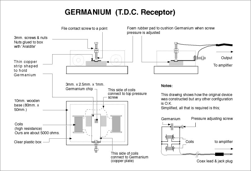
(Figure 4: Germanium TDC Receptor)
The original intended use of the Germanium TDC Receptor for retro-death-telegraphy
is discussed extensively in the book “The Scole Experiment” by Grant
and Jane Solomon. I will not go into detail about this here, instead
here is a link to a recording of the output from one;
(Source; https://archive.org/details/TransDimensionalCommunicationExperiment)
The Germanium TDC Receptor was chosen as an input source as it seems to be the best guess as a means of channeling information from the Tao/Cosmic Mind (assuming such a thing/non-thing exists).
The raw output from the Germanium TDC Receptor would be amplified using an LM386 amplifier chip;
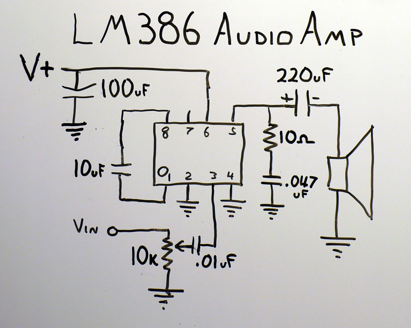
(Figure 5: LM386 amplifier chip schematic)
This signal would then be fed into the analogue input pins of an Arduino.
This whole setup would be housed in an ultra-weatherproof metal casing with solar panels on the top to power the system;
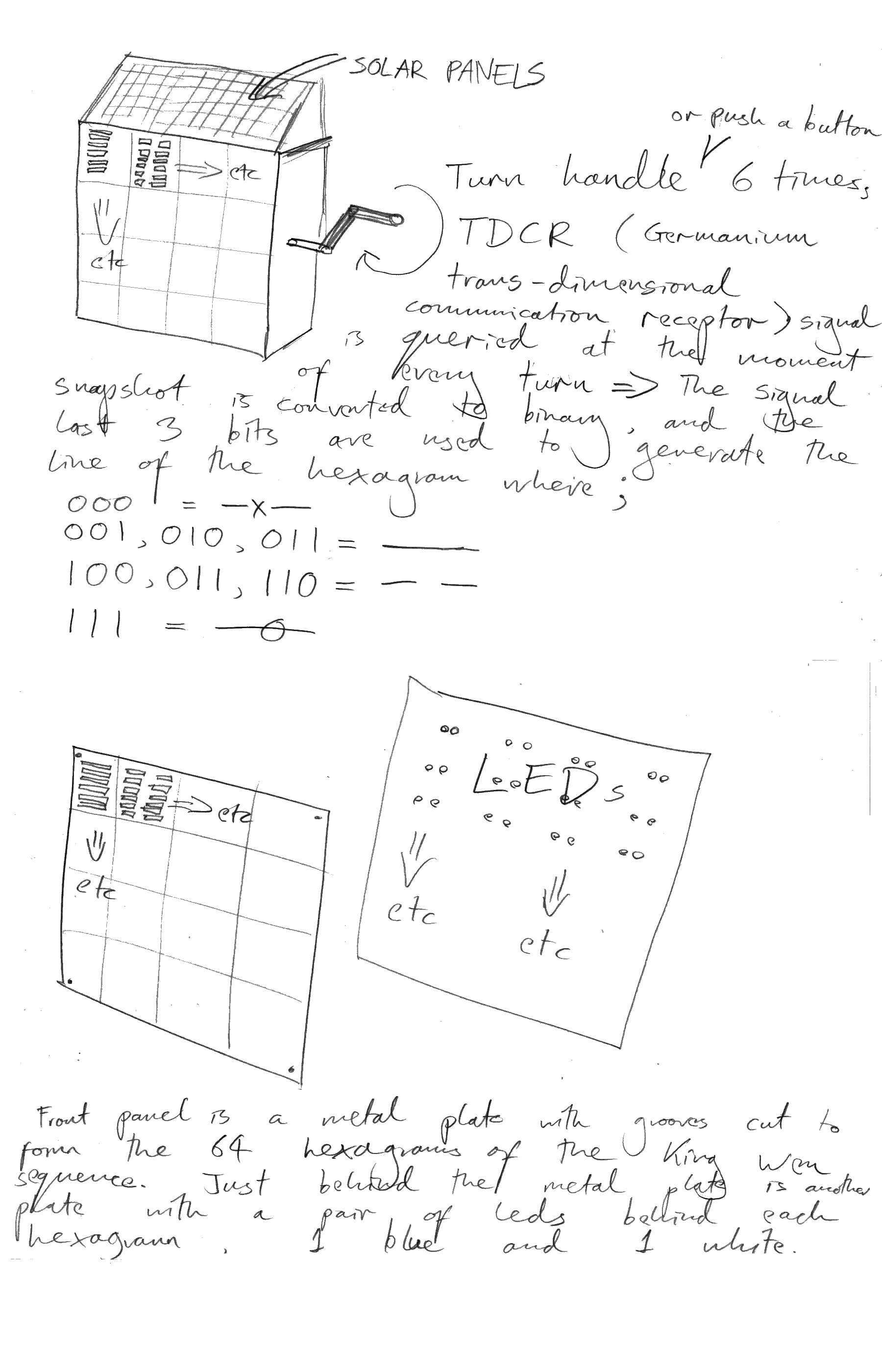
(Figure 6: Overview of system)
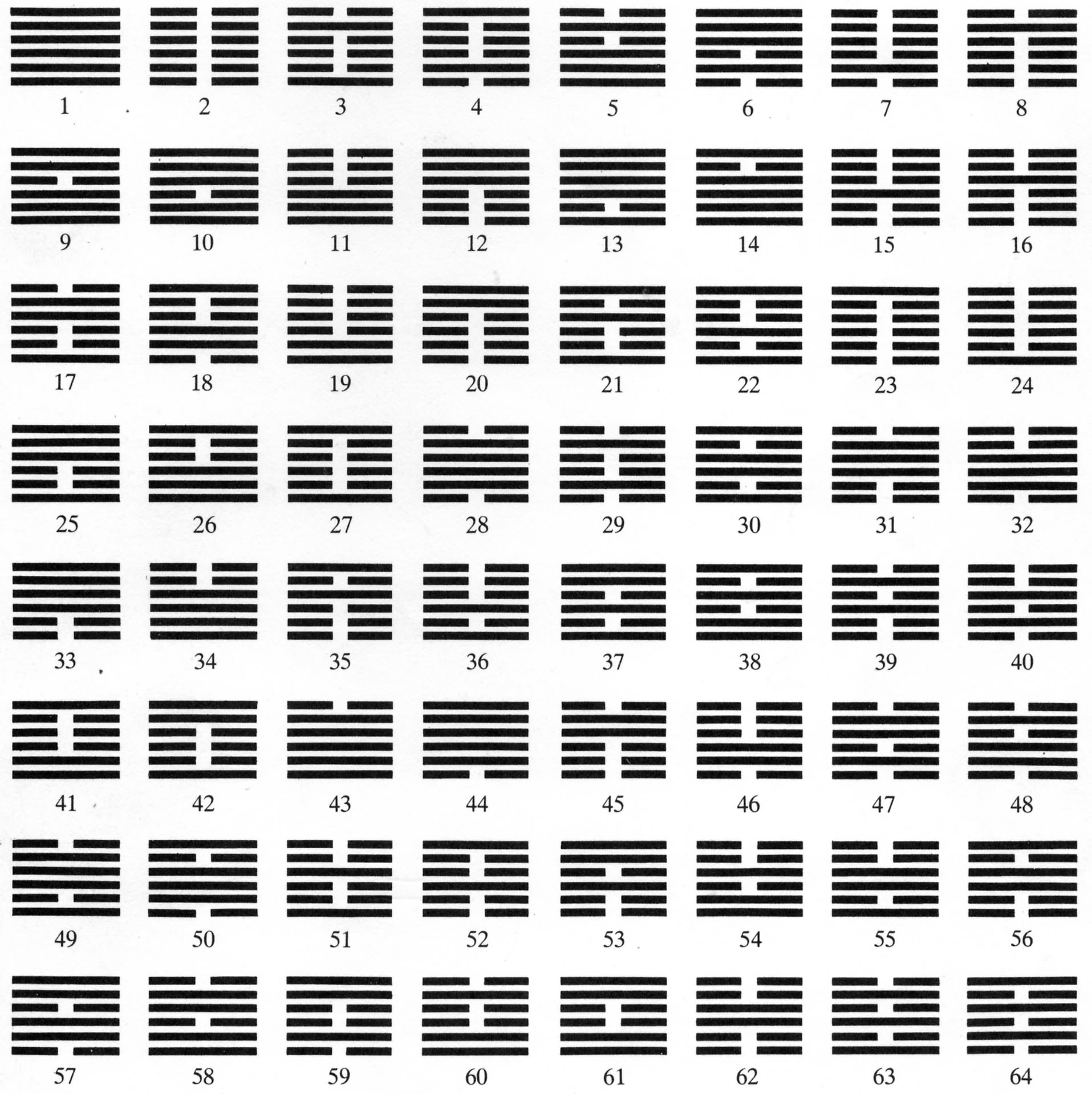
The front panel of the metal casing would have slits cut into it to draw the hexagrams of the King Wen Sequence in an 8×8 configuration.(Figure 7: The King Wen Sequence)
Behind the front panel would be another panel with an array of LEDs, two behind each of the hexagrams (1 white, 1 blue).
A similar setup and size to this (image taken from http://forum.arduino.cc/index.php?topic=55693.0);
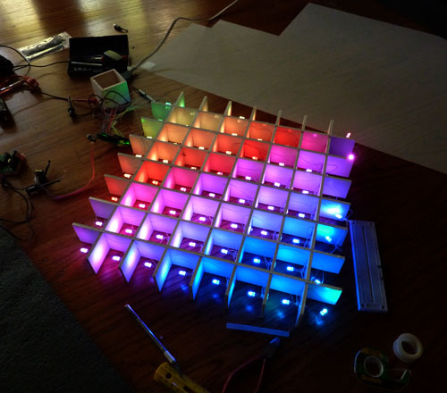
This would be encased in a waterproof transparent casing, and the metal front panel with the hexagram slits cut out would sit on top of it, so that the light would shine through the slits. The material dividing the squares would be an opaque material such as wood or metal, so that when a particular hexagram lights up the ones adjacent don’t light up a little bit as well.
On the side of the casing would be a handle, and a reset button (reset button not shown figure 3). The user would keep in mind his or her life question whilst turning the handle 6 times. At the moment of every turn, a snapshot reading of the amplified output from the Germanium TDC Receptor would be taken. At the moment of every turn, all of the LEDs would flash, all the white then all of the blue alternately until the handle has been turned 6 times. This figure would be converted to a binary number and the last three bits of the number would be used to generate a line of a hexagram, in the same way as with the turntable setup. Hexagrams are generated from the bottom up, i.e. the first turn determines the bottom line of the hexagram, as this is how plants grow. The rules for converting the generated binary numbers into lines is as follows;
⦁ 000 = Old Yin (—X—)
⦁ 001, 010, 011 = Young Yang (———)
⦁ 100, 101, 110 = Young Yin (— —)
⦁ 111 = Old Yang (—θ—)
Once the handle has been turned 6 times we will have generated a hexagram. The appropriate white LED would then light up behind the generated hexagram, representing the present. If the generated hexagram had any moving lines (i.e Old Yin or Old Yang) then we would also be able to determine the transformed hexagram. The transformed hexagram, also referred to as potential, the future, or underlying influence, is calculated by the rules; Old Yin becomes Young Yang, and Old Yang becomes Young Yin. This is fundamental I Ching philosophy, and applies to the previous I Ching Turntable project, remember it! The appropriate blue LED would light up behind the transformed hexagram.
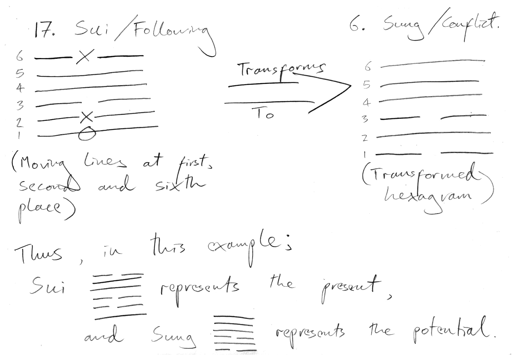
For example, if we generated the hexagram;
So, in the above example, the white light behind Sui would light up, and the blue light behind Sung would light up.
The box will have a reset button, the system will also reset itself if left for a length of time. Its reset, default setting would be to take snapshot readings of the amplified Germanium TDC Receptor signal. The point in time these readings will be taken will be triggered by a 555 oscillator circuit, the speed of which is determined by a positive temperature coefficient (PTC) thermistor or posistor. This means that the resistance increases with increasing temperature, the circuit will be rigged up as per figure 5 and 6 below. Figures 5 and 6 show a test circuit with a flashing LED. The speed of this flashing LED represents the sampling rate of the Germanium TDC Receptor signal in the actual system. In this circuit, as the temperature (and resistance) rises, the speed of oscillation slows;
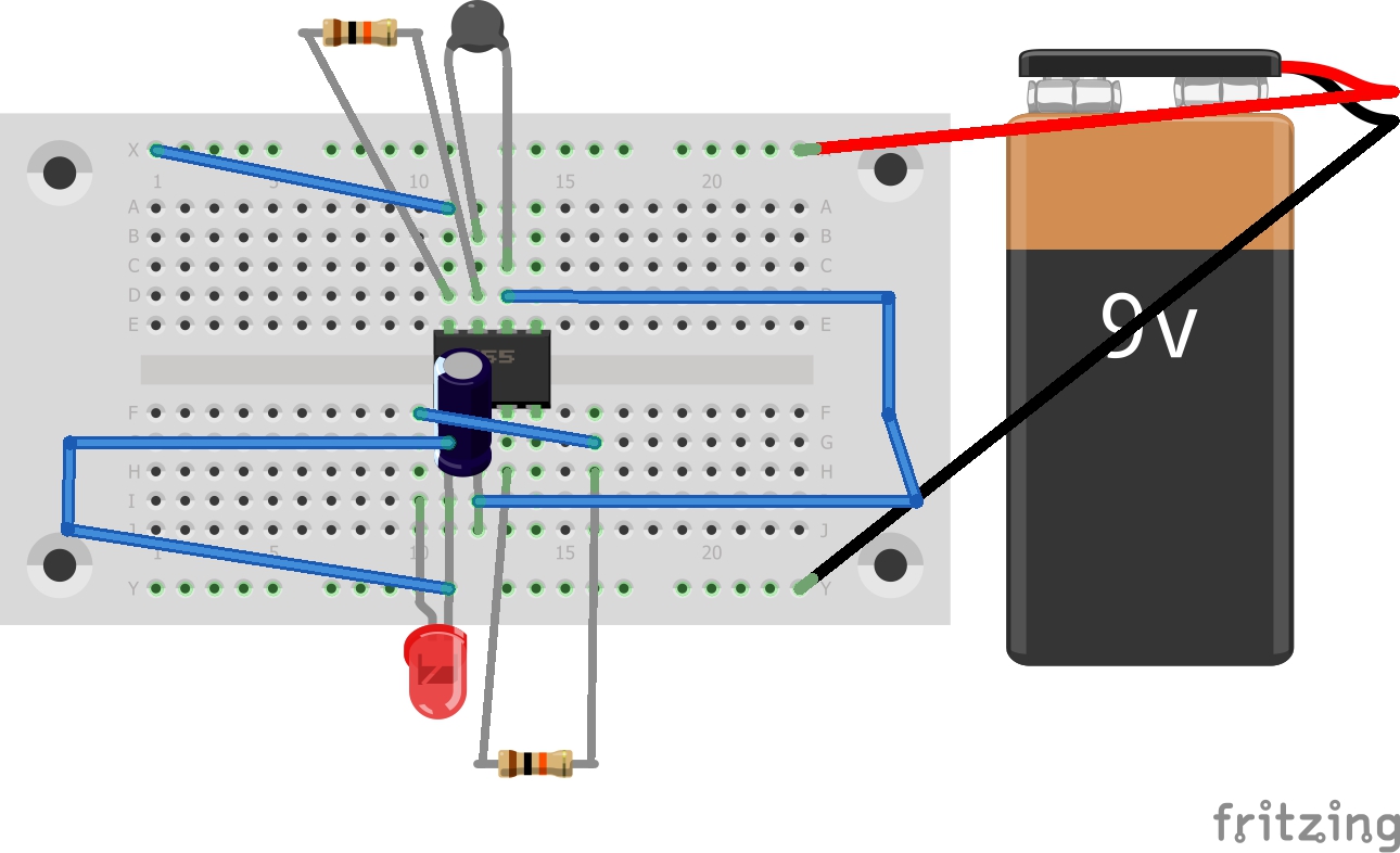
(Figure 8: Posistor (PTC) with 555 timer chip test setup, breadboard view)
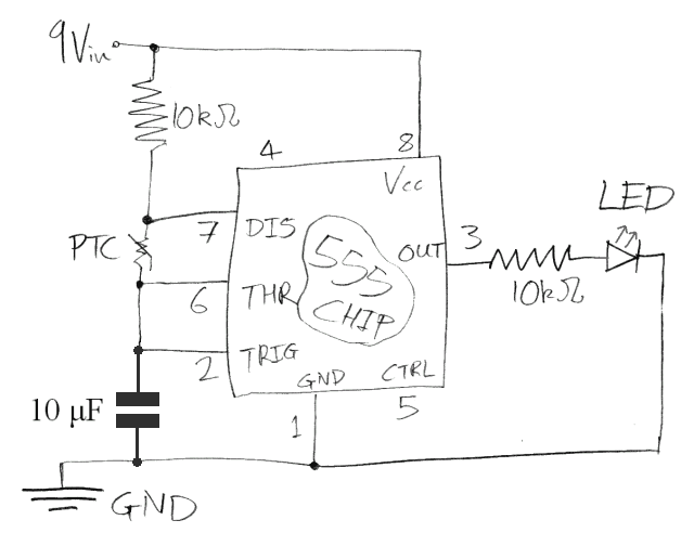
(Figure 9: Posistor (PTC) with 555 timer chip test setup, schematic view)
Here’s a video of me using a potentiometer in place of a PTC in the
above circuit to ascertain whether the speed of oscillation rises or
falls as the resistance between pins 6 and 7 on the 555 chip rises and
falls;
Controlling a 555 Oscillator Circuit with a Potentiometer. from George Haworth on Vimeo.
The philosophical rationale for this technical decision should be clear when one considers this quote by Terrence McKenna (taken from the opening sequence in the film “Manual Of Evasion LX94“);
“Time is biological. Time is made by the rhythm of metabolism, time
is the unfolding of cellular processes, the transcripting of protein,
the building of membrane, the transport of materials. Time is a
phenomenon created by life itself. Time, temperature and weather are all
related through the concept of change. They are in fact varieties of
change. And time and temperature are very intimately related in
invertibrate, cold-blooded animals.
As the temperature falls, time speeds up, as it rises, time slows. This
is why for an insect, a grasshopper, the night seems to pass instantly
and the long day lasts forever.”
So I thought a good title for this piece might be “What time feels like for a grasshopper”.
As for a location, on top of a mountain in a far away land. I’m going to see if I can install it on Holy Island off the West coast of Scotland at the highest point on the Island.
Here’s a picture of me at the highest point on Holy Island, I would attach the installation to the triangulation pillar I am leaning on (assuming they give me permission):

References (not previously quoted)
– The I Ching text was the Richard Wilhelm Translation (1950) taken from; http://deoxy.org/iching
– Special thanks to my girlfriends mate Shelly who kindly gave me the Raspberry Pi in return for me DJing at a party for her. Nice one